Showing posts with label Arduino. Show all posts

Monday, September 10, 2018

Getting Started with Adafruit Circuit Playground Express book now out from major booksellers!


Out today September 10th! A new paperback book on the Adafruit Circuit Playground Express board! The book gets you started with microcontrollers by learning how to use the Express with Microsoft MakeCode and CircuitPython. There is also information on configuring and using the board in the Arduino IDE.
Now available from online bookstores like AmazonBarnes & NobleAmazon.co.ukamazon.ca, and booktopia.com.au.
The book will also be available from Adafruit to include bundling with Circuit Playground Express, stay tuned.
Have all the information at your fingertips in this new book. Check it out today.

Saturday, July 14, 2018

New Book: Make: Getting Started with Adafruit Circuit Playground Express


My new book Getting Started with Adafruit Circuit Playground Express: The Multipurpose Learning and Development Board from Adafruit was released earlier this month in a Humble Bundle in eBook format. The final print and eBook will be out in September, hopefully available at World Maker Faire in NYC September 22 and 23.

Prerelease buy on Amazon: Getting Started with Adafruit Circuit Playground Express: The Multipurpose Learning and Development Board from Adafruit


I should be at Maker Faire NY - stay tuned for when and where and plan to come & have fun hanging out with the Makers!

Saturday, February 4, 2017

Can Raspberry Pi Zero Take Arduino Projects to New Greatness?

Although Arduino prices have gone down from their $35 price a couple years ago, they are still in the $20 range. This affects the cost of projects built with Arduino.

The Raspberry Pi Zero was introduced a few months back at an affordable $5 price point. Many, many articles have been published trying to compare the Raspberry Pi boards with Arduino. It is mostly apples vs. oranges. Why?

The Raspberry Pi boards are full Linux computers in affordable packages. Arduino is a microcontroller platform with great ease of use. Each has their strengths and weaknesses.

What I'd like to focus on is the Raspberry Pi Zero. We are starting to see more projects that use the Zero where previously you might have used an Arduino. Why would people do this? Is it appropriate everywhere? No. Let's see where a Pi might be more applicable than an Arduino.

1) Memory is more plentiful on a Pi. Doing some large number of things or controlling a large number of RGB LEDs for example, you can run out of memory on many Arduinos. Not so on a Pi.

2) Displays on Arduino tend to be small as it requires buffering in the microcontroller (memory intensive) or via a separate display with memory buffer (expensive). All Raspberry Pis support both HDMI and composite video.

3) Networking via wired or wireless is available on Arduino. But it isn't straightforward and the user must process a lot of things. Linux was born in the network world so there is a great deal of software built in to handle communications. All Pi models except Zero have a network jack, The Pi 3 has wireless. Pi wireless via USB us fine as software is usually available.

4) Audio is possible on Arduino with separate add-ons. It is built into the Pi. Recording audio is near impossible for any length of time due to memory but replay of wav files on SD card works fine as long as you are not doing much else.  If you use a Pi Zero, the best audio takes an add-on board also.

5) Size matters, and the Pi Zero is smaller than many Arduino boards.

6) Software: nearly any software package that has been written on a Linux system (apart from large server applications) often will run on a Pi, It is harder writing some complex specialized input/output programs or drivers that may not be available already. Use of Python easy, C and C++ is ok, specialized languages like Javascript, Perl, Ruby, PHP are all available. BASIC, FORTRAN, etc. can be found but they are not Pi optimized.

Where the Arduino wins over the Pi:

1) Analog input/output - the Pi series has no built-in analog inputs.

2) Real-time control - the Pi has Linux overhead so anything needing strict timing is better on Arduino if it fits.

3) Software: a huge amount of real-time software libraries have been written, mostly in C/C++. There are other languages like Micropython available but they are not widespread.

I'm a firm believer in taking a look at all available hardware and software to be informed on what is best for the application. I know something like the Pi 3 or Pi Zero will not be a replacement for an Arduino for some applications. But the Pi price point and capabilities makes sense for some projects that might take an Arduino with several add-ons or a more expensive variant.


Friday, January 13, 2017

Arduino as a Microcontroller Reference Platform

The Arduino line of microcontrollers has, arguably, been the spark that brought programmable hardware to Makers worldwide. This article takes a look at how Arduino furthered the use of microcontrollers and how it is important defining standards today.

Arduino dates back to Hernando Barragán's design of the Wiring platform in 2004. In 2005, Massimo Banzi, with David Mellis forked the Wiring source code and started running it as a separate project. Arduino use grew through successive product releases including the Arduino Diecimila, Arduino Duemilanove, and the baseline Arduino Uno board series (in its third revision). The evolution set the Atmel ATmega328P microcontroller in the Uno to become the microcontroller standard of its time.
The Arduino Uno R3 (photo via Adafruit)
The ecosphere of Arduino, consisting of the circuit board and Arduino Integrated Development Environment (IDE) became very compelling for developers. Many software libraries were created to extend Arduino software capability and hardware connectivity. This growing capability launched the ATmega328 into many project designs. The success of the Uno board design led to other companies and makers to make Uno compatible boards based on the '328. The price of the Uno was set at the time at $35 and it did not go on sale often, requiring an investment on the purchase of each board.

In expanding the Arduino product line, the Arduino team introduced other boards based on newer microcontrollers. Some have been more widely adapted into maker designs than others. Many software libraries required changes to support different microcontroller architectures.

The development of the Atmel ATmega328P has evolved from the ATmega168 and smaller ATmega8, which all use the Atmel's AVR architecture. The '328 chip runs at a nominal 16 MHz (on the Uno) with 32 kilobytes of flash memory. This is modest by computer standards, but this chip equalled much of the industry when it was introduced.

The Arduino team, in looking for better designs, introduced the Arduino Leonardo. Leonardo was based on the Atmel ATmega32U4 microcontroller with the same 32kB of flash at 16 MHz. The chip was mostly compatible with the '328 but also had the feature of native USB controller onboard, eliminating the need for a separate USB chip on boards such as Uno. The Leonardo was less popular than the Uno but found some interesting uses due to features not found in other microcontroller boards. The native USB was very popular with other company/Maker board designers who, to this day, use the ATmega32U4 and the Leonardo software to make compelling microcontroller boards at a low cost.
Arduino Leonardo (photo via arduino.cc)
Sadly the Leonardo has been discontinued by the Arduino team but the use of the ATmega32U4 lives on in many new designs.

The Arduino Due was the Arduino team's first commercial step into the Atmel SAM architecture chips. SAM features an ARM processor, capable of speeds much higher than the Uno/Leonardo 16 MHz and also capable of more flash and other compelling features. The Due, being the first Arduino SAM board did (has) not find (found) a wide following in products or maker projects but it did (has) start software migration of the Arduino software base to use non-AVR chips. (Note: While announced as discontinued, they are still available via arduino.cc).

Note: Yes, I am skipping some Arduino releases here and there which are also AVR based designs.

The 
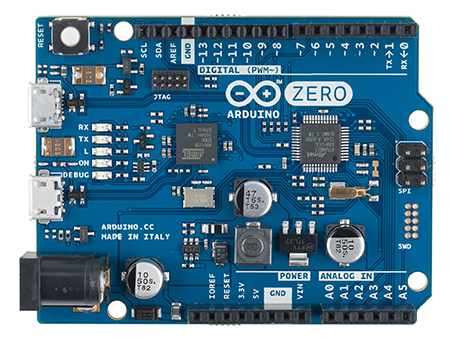
Arduino Zero, beta tested in 2014 with release in 2015, has become the new tier for microcontroller designers. Based on the newer Atmel/Microchip SAMD series, the board provides the SAM higher clock rates, ARM core, and a much smaller size.

Microchip recently bought Atmel, hence the processor provider name change.

The Zero has not supplanted the venerable Arduino Uno, yet, but the day draws closer where there are no arguments for selecting the more modern chip. Variants are smaller and much easier for manufacturers to incorporate. The Arduino Zero software is defining a new generation of compatible boards, especially from Adafruit.com which is revising a number of their microcontroller boards to use the SAMD chips. The third party boards are often less expensive than the Zero as the Zero design uses an additional debug hardware chip not used by most hobbyists.

It is conceivable that Microchip may look to discontinue AVR production through price hikes, leaving the SAMD and possibly their own PIC lines more widely available.
Arduino Zero (photo via Adafruit)
Where does the flood of Arduino compatibles leave the Arduino team?  Actually in a fairly good spot. The team are the Research and Development group foremost, providing both the low level chip firmware and the ever more powerful IDE to tap into new chips. The Arduino team continues to bring forward very compelling boards in different form factors: the Arduino Zero, MKR1000, and MKRZero boards have a great amount of capability at a cost lower than the Arduino Uno of old.

The Arduino team also has been collaborating on non-Microchip boards, including Arduino Yun, Arduino 101, and others. They also are important in expanding both the capabilities of the Arduino ecosphere and in partnering with companies other than Microchip to include Intel. The ability to easily use new, powerful microcontrollers and Linux based processors only benefits the ability of both companies and Makers to use the newer processors.

We all can look forward to the growth of the Arduino family tree, which has grown from a seedling over ten years ago. The innovation of the Arduino team has enabled people worldwide to harness some incredible hardware in making incredible products.

Sunday, June 19, 2016

Arduinos, New Arduinos, and Pin Header

With a new crop of Arduino compatible boards in "non-traditional" form factors, you may need to consider what type of header pins you want to use on the boards.

Pin header is typically used for:
  • Easier connection to a breadboard or to connect wires (electrical)
  • Connecting other boards via stacking (mechanical)
Below is the classic Arduino stacking header shield (for prototyping) and that board stacked on an Arduino R3 (right). The shields for the classic Uno R3 are an 8 pin + 10 pin header on top (half-pin space between), and a six pin and 8 pin header opposite (one pin space between, some boards put a nonfunctional header pin between like on the new Arduino Uno WiFi). Boards made since the Arduino Zero have an additional ATN pin on the side closest to the power jack.
Arduino Stacking Shield with female header with long pins (via adafruit.com)
A shield will need long male pins beneath and the Arduino typically has female pins on top to make the connection.  Note the shield above has female pins on top so another shield may be stacked on top of that.  If a shield does not need to have another shield stacked on top, you can use plain male header.
Arduino compatible Feather with long female pins for Breadboard, display "shield" on top with male non-stacking pins (via adafruit.com)
The pictures above demonstrate several things: The Adafruit Feather arduino-compatible board on the left has female header with long male pins to be able to be pressed into a breadboard.  The display on top has regular male pins soldered on.  The picture on the right shows the two types of header.

Mail order companies (Adafruit, Sparkfun, Farnell, eBay, etc.) sell a lot of different types of header for your making use. Male, female short, female long, single row, double row, and header with 90 degree bends. Male header even comes in extra long for certain applications. Header can come in many widths, the most common when buying header alone is in 40 pin pieces/sticks, although vendors will often sell shorter lengths for specific purposes.

A few different types of header (yes there are many more types)
Most header is built with a tenth of an inch spacing between pins (0.1" or 2.54 millimeters metric). For some items like XBee radio and some ESP8266 breakouts, they use 2 mm spacing, and some boards may use other spacings. Be careful on guessing the spacing for certain components, boards, displays, etc. Always measure or count twice.

Now on to some of these new Arduino compatible boards coming out. The header pins in the Arduino R3 pictures are nice but they are usually made for 14 on the short side and 18 on the other side. These will not work on some other boards.  Here are the header pin counts for some modern boards:

Adafruit Feather has 12 pins on one side, 20 on the other

Arduino.cc MKR1000 has 14 pins on both sides

The Adafruit Huzzah ESP8266 Board has 10 pins on either side (they give you a few extra pins in the header strips)

The NodeMCU ESP8266 board has 15 pins on either side

Making Custom Header Widths


If you have header that is longer than the board you need it for, you can usually cut the header pieces to fit. This may also save money, buying 40 pin sticks and cutting to fit your project.

You should wear eye protection and use caution when preparing to cut header, pieces will fly off!!

Use a good pair of diagonal cutters.  Some header, like the male ones, have a groove between pins, making it easy to make a clean cut (often called "breakaway header").  Female header is trickier. Center the cut about in the middle of the next pin after counting out the number you need.  Make a straight cut.  Be careful as the gold pin will fly out

Cutting male header (left) and female header (right).  Via learn.adafruit.com
This will leave that side with a bit of a U shape. You can use good cutters to do further trimming. Then use a file to get a nice smooth edge.

Soldering Header


The secret: Use a breadboard or another board with header pins to hold the board to be soldered in place. Have a hot soldering iron and heat each pad+pin and solder.

learn_arduino_solder5.jpg
Using one board to hold pins for another (via learn.adafruit.com)

With a breadboard, put the pin header in, then the board, then solder.  You can also put a piece of male header in a breadboard to secure a female header to solder onto a board (a good use for the extra-long male header). Be sure the board you are soldering is level, once the solder cools, it is hard to level out.

What are your tips for using header in your projects?

Saturday, April 9, 2016

Use Adafruit Feather Wings as MKR1000 Shields

The MKR1000 microcontroller board from arduino.cc is a very new, very powerful board. With the board coming out of beta and now available, the pinout of the board is fixed (compared to the "pinout might change" communicated in the beta).

It will take some time for MKR1000 compatible daughterboards ("shields").

Fortunately, Adafruit makes add-on boards for their new Feather line. Feather comes with several different microcontrollers: AVR 32u4, SAMD21 M0, ESP8266 and some also come integrated with nice radios. Peripheral daughterboards (Adafruit calls "Wings") now available include LEDs, a real-time clock, motor control, relay, servo, and OLED display.

In the absence of MKR1000 shields, you can look to use Feather Wing boards.


Wings are not directly pluggable into headers placed on the MKR1000.  The pinouts are different and the M0 processors on the Feather M0 and the MKR1000 are different (SAMD21 vs. SAMW25 respectfully).

To overcome the differences, a sandwich board can be used. This would best be a custom board (think a nice purple PCB with ma1e headers on the bottom, female on the top). with the pins from the bottom switched around to make the top pins fit the Feather Wing pin expectations.

For a proof of concept, I took two Adafruit Proto Feather Wings. They were used to make the wiring changes.

Above, the MKR1000 is the bottom board furthest from the display.  It has female headers (with extra long pins for breadboard use also) soldered in (shown below).


The second board, a proto, has two sets of male pins, ones to make with the MKR1000 and male headers pointed up towards the second proto.

The second proto has male headers pointing down to the first and female headers for the Feather Wing daughterboard.

The cross connection may be done with 22 gauge wire.  A more old fashioned connection method is to use fine wire wrap wire and connect with a wire wrap tool. See Wikipedia if you're unfamiliar with wire wrapping.

The OLED Feather wing communicates via the I2C bus. To make it work, we need to cross connect the following pins:

  • Ground
  • Power / 3.3 volts
  • I2C data line (SDA)
  • I2C clock line (SCL)
  • The reset line for the display is connected to Pin 5 on the MKR1000
The code to put test text on the display:


/*
 *  MKR1000 and Adafruit Feather Wing Code
 *  Mike Barela http://21stdigitalhome.blogspot.com/
 */
#include <Wire.h>
#include <Adafruit_GFX.h>
#include <Adafruit_SSD1306.h>

#define OLED_RESET 5
Adafruit_SSD1306 display(OLED_RESET);
#if (SSD1306_LCDHEIGHT != 32)
#error("Height incorrect, please fix Adafruit_SSD1306.h!");
#endif
void setup() {
  
  // by default, we'll generate the high voltage from the 3.3v line internally! (neat!)
  display.begin(SSD1306_SWITCHCAPVCC, 0x3C);  // initialize with the I2C addr 0x3C (for the 128x32)
  
  // Show image buffer on the display hardware.
  // Since the buffer is intialized with an Adafruit splashscreen
  // internally, this will display the splashscreen.
  display.display();
  delay(2000);
  // Clear the buffer.
  display.clearDisplay();
  display.setTextSize(1);
  display.setTextColor(WHITE);
  display.setCursor(0,0);
  display.print("Connected to");
  display.setCursor(0,16);
  display.print("MKR1000!");
  display.display(); 
}
void loop() {
}
Have fun wiring additions to your MKR1000 board including using Adafruit Feather wings.

Wednesday, March 2, 2016

Getting Started with the Beta Arduino MKR1000

Note: No, I cannot share the pinout of the MKR1000 beta board (printed on the back of the board) per an email sent to the Hackaday.io contest winners, sorry.  The reason is the pinout might change so making shields right now would lead to heartache.

One thousand Arduino.cc MKR1000 beta boards are now being received by Makers worldwide thanks to a contest sponsored with Hackster.io and Microsoft.  Round Two of their competition is to make some great things.  Here is documentation on how to get started after the box comes in the mail.

1) Go to the e-mail you got days ago stating that you shouldn't release info (doh!).  Sign up for the MKR1000 closed forum on arduino.cc and wait up to 48 hours for the link (doh!).

2) Go to the arduino.cc download site and get the nightly build of the Arduino IDE software.  Copy it into a directory to use out of the zip file.

2a) For Windows users only: go into the drivers directory and run program dpinst-x86.exe for 32 bit Windows or more likely for modern installs dpinst-amd64.exe for 64 bit Windows (Intel or AMD, not just for AMD processors).  This will install the device drivers for the latest Arduino boards including MKR1000.

3) Run the beta Arduino IDE by running arduino.exe.

4) Go to Tools -> Board -> Boards Manager and install the Arduino SAMD Boards package version 1.6.3.  This gives you the MKR1000 as a board choice.  1.6.4 apparently dropped MKR1000.  If the closed MKR1000 forum says differently use what they say.

5) Go to Sketch -> Include Library and do a search for "101".  Install the WiFi 101 library package which supports the MKR1000 wi-fi support. Use version 0.8.0 or higher.

6) Plug in a USB cable A to Mini B from your PC to the board.  For Windows, the appropriate driver should load if you got the beta IDE driver installed ok - if the driver fails, try again to install the driver.

7) You can load the Blink sketch:

void setup() { 
  pinMode(6, OUTPUT);     // Pin 6 is onboard LED on beta MKR1000 

void loop() { 
  digitalWrite(6, HIGH);  // turn the LED on (HIGH is voltage level) 
  delay(500);             // wait for 500ms 
  digitalWrite(6, LOW);   // turn the LED off by making voltage LOW 
  delay(500);             // wait for 500ms 
}

Note the LED on the beta boards is on Digital Pin 6, not the usual Arduino Pin 13.  If all goes well the Green LED marked "L" blinks!

There are more sample programs for advanced use including web client and server under File -> Examples -> WiFi 101. Note the Wifi 101 has its LED on Pin 9 which has to be changed to Pin 6 for MKR1000.  Try the SimpleWebServerWiFi sketch with the LED ad Pin 6, very fun!  You'll need the output from the serial monitor to know the web address for the web page to change the LED state.

Resources on the Internet


Tuesday, February 23, 2016

Arduino.cc Discontinues Selling the Arduino Due

Photo credit: Adafruit

In a post on the Arduino.cc developer's email list, team member Massimo Banzi stated on February 23, 2016:
When we rebuilt our manufacturing network we took the chance to redesign the product line to simplify it. We also had to decide the sequence of release giving priority to products that are most popular. Having said this we see an interest for the Due from the resellers and we’re working on a solution. In the meantime the SAM core is still supported and it’s getting updated even if we’re not selling the hardware.
He goes on to clarify:
Arduino/Genuino doesn’t sell the Due full stop.  There is a number of companies using the Arduino name and logo around the world who make boards that are called Due. As I said we’re evaluating an improved product for this market segment. 
So:

1) Software Support: No worries, the Arduino.cc IDE has support for even ancient Arduino versions listing "Arduino Duemilanove or Diecimila" and "Arduino NG or older" in the current IDE.

2) Due Chip: may possibly be on future Arduino.cc products but not the exact Due board.  Atmel also makes many variants of their chips allowing board designers to have flexibility in choices.  Time will tell.

3) Due Board: Will not be sold by Arduino.cc or under the Arduino or Genuino brands.  Any new boards will most likely be from Arduino.org or Chinese clones. The ecosphere is still free to sell derivative Due compatible boards which should be around for quite some time.

The Arduino.cc website still lists the Due in the shop but "Out of Stock".  Banzi posted the website will be amended soon.

Thoughts?  Does this complicate your decisions or do the capabilities of new boards like Arduino Zero and Arduino 101 fill the void?


Saturday, February 20, 2016

The ATN Pin on New Arduino 101 and Arduino Zero

If you look at the pictures of the new Arduino (.cc) Arduino/Genuino 101 and Arduino/Genuino Zero, next to the IOREF pin you will see a new pin.  Formerly undefined on AVR (ala Uno) style Arduinos, the pin is now labelled ATN.


Currently there is not much information on use for this pin except one forum.arduino.cc thread. There, Cristian Maglie of the Arduino team explains:

The ATN pin is an experimental feature we're introducing with the Arduino Zero.
Many shields and expansion modules use an SPI communication protocol and this always requires electing a pin to act as  "chip select" effectively making one extra pin unavailable. On processors that have more than 28 pins there are usually extra unallocated pins that can be used. We decided to experiment and allocate a pin to act as the default chip select for the first shield/module on the bus.
We're going to issue a more formal "application note" to explain some of the new features provided by this pin. For now just treat it as one extra pin available for you to use.
In the Arduino IDE, it is defined as ATN when you select a board that supports it.

Use


SPI use on Arduino is discussed in this reference.  TO use SPI, you connect to the SPI bus, often on the ICSP connector.
The only pin that is needed but not on this header is the Select line to select a particular SPI device on the bus (often called a Slave Select or SS pin).  For this purpose on most boards, you can use any digital or even an analog pin.  But this will take away a pin that could be otherwise useful in your project.

As modern processors have alot of digital pins, more than are used on the standard Arduino shield pinout, a extra pin has been provided for your use, ATN, ostensibly to help you use that as the SS pin function freeing the digital pin you might have had to use for other uses.

More will be posted when use of this pin is more widely published.


Wednesday, February 10, 2016

Board generic (platform esp8266, package esp8266) is unknown

Today's time to update my Arduino IDE (arduino.cc) to version 1.6.7.


With the new environment, I needed to update the Boards Manager to add support for the latest and greatest boards.  Adafruit has introduced some nice boards including their Feather line, which I want to work with.  So I update the Adafruit AVR boards, then the ESP8266 Boards.  The ESP support requires a download of 153.5 megabytes.  Wow.  I mistakenly interrupted the download to do something else.  Mistake!

When I needed to program an ESP device, I redid the ESP board support.  But every time I tried to program any sketch, I got the error message:

   Board generic (platform esp8266, package esp8266) is unknown

Uninstalling and reinstalling the IDE did not help.  I finally resorted to a Google search and found this Wordpress blog post.  Thank you!

So for Windows:

  1. Close the Arduino IDE windows that may be open.
  2. Go to the directory C:\Users\yourusername\AppData\Local where yourusername is the user name you are logged into.  
  3. Copy the preferences.txt file in the Arduino15 subdirectory somewhere like your Desktop
  4. Rename your Arduino15 directory to Arduino15-old.  Create a new Arduino15 directory and copy back the preferences.txt file into the new (now clean) Arduino15 directory.
  5. Now you can open the Arduino IDE and it will be clean of any board preferences.  Go to Tools -> Board -> Boards Manager and add support for the boards you want to use (such as ESP8266, etc.)
Now, if you by chance don't see the ability to add ESP8266 support or Adafruit support, you need to add something to your preferences.  Open File -> Preferences.  On the line Additional Boards Manager URLs: add the following text all on the same line:

https://adafruit.github.io/arduino-board-index/package_adafruit_index.json,http://arduino.esp8266.com/package_esp8266com_index.json

Press the Ok button.

Now close the Arduino IDE and reopen it.  You should now see the additional boards that you may want to use.

Again, thanks to the ESP8266Hints blog for the pointers.

Saturday, April 25, 2015

Arduino Packaging

Adafruit made an interesting suggestion regarding the Arduino vs. Arduino lawsuit. Adafruit noticed that the packaging for the Arduino Uno and Leonardo includes a pamphlet that states:

Manufactured under license
from Arduino by
SMART PROJECTS S.r.l.

Smart Projects is the former name of Arduino Srl. Arduino Srl is claiming to be the trademark holder and has forked the Arduino IDE.

If Arduino Srl feels they own the trademark, why would they include this statement in their packaging?


Here are my package inserts from retail Arduino packages over the past couple years.  They all have the license text.

Unlike Sparkfun who decided to walk a line between the companies, I believe the Arduino.cc - the original founders - as holding the Arduino ecosphere rights (it was their creative work from which the project was born).

Monday, April 6, 2015

Using the Arduino IDE to Program the Raspberry Pi and Other Devices

Ever wish you could prototype a Raspberry Pi program as easily as prototyping on Arduino?

The Arduino IDE allows nearly any processor to be programmed with the same easy to use language. Back in 2012, this was possible: it takes architecture changes by the Arduino group (arduino.cc), some programming by code library developers (adafruit.com, sparkfun.com, many others), and from users to get all of this working.

The parts are now in place to do this: the latest Arduino IDE releases are in a new 1.6.x branch, the latest as of this article is 1.6.3.  This release is revolutionary in having the following:
  • A new library manager - libraries can be installed with several clicks from a website without downloading code and installing it in a specified place on the user's PC.
  • The capability to specify new boards that are not quite the same as Arduino boards. Companies have done this by hacks and creating special versions of the Arduino IDE which can get confusing after a bit.
  • A mechanism to easily specify and use code compilers other than the Atmel AVR.  The Atmel SAM series is available after installing the 1.6.3 version if you request it. 
In the same manner as the SAM (Arduino Due) capability can now be an add-on once the initial IDE is installed, other companies are working (quickly) to add the capability to incorporate their products. Obvious candidates include:
  • Non-Arduino Atmel AVR boards
  • Arduino "compatibles" - like the Teensy series which is very popular
  • Boards based on ARM cores Cortex M0, M0+, M3, etc.
Take this a step further.  While running "simple minded microcontroller code" on more powerful boards seemed nonsensical not long ago as cost inefficient, those costs have plummeted. Development boards using powerful processors have come down in price thanks to Raspberry Pi, BeagleBone, and many others.  The $50, $35, $25, $12, and $8 price points all have different boards that can be used.  Even at $2 to $5, new boards like the ESP8266 Wifi controller are coming in.  So, extend your thought to using the Arduino IDE to actually run Arduino code (not just program an AVR) on:
Some will say "Why Arduino?"  The Arduino IDE and language specification, started in 2005 and extended since, has a proven track record for allowing users to easily get code running that actually interacts with the "real world".  Millions of lines of Arduino code have been released under open source licenses, allowing reuse by anyone. With such a vast repository, why not leverage this onto other microcontroller and microcomputer architectures?  With the compatibility to use C and C++ code, it is even more compelling.

Raspberry Pi as an Arduino Target


If I have some interesting Arduino code, say for controlling a near-field card reader, and wanted to port this to Raspberry Pi, I'd face a tough choice.  Think about reprogramming in Python and hope there is manufacturer library support for Python, or consider programming in C and know that I'd have to rewrite the Arduino library to work on the Pi.  Unsavory choices.

If the Arduino IDE would create a Raspberry Pi Linux executable of my Arduino sketch (program), I'd be nearly done.  Due to differences in programmable pin (GPIO) numbering, some items would require changes but those are numbers and not wholesale code structure changes.
This could increase (rapidly) the available uses for a Raspberry Pi.

With a huge body of Open Source coders who may have the interest and time, I looks like there will be many more places where we will see Arduino code running.


Tuesday, October 7, 2014

Triggering Ten Pins with Four Outputs

A common issue in microcontrollers: what do you do when the pins on your controller do not match well with the outputs to your controlled items?  This is something I wanted to write about in Getting Started with Adafruit Trinket but I was over on page count as it was, so I'll post it here for you.

What the designer may not normally think about is using TTL logic chips.  Often called 74 series after the original numbering by Texas Instruments, there are hundreds of pre-existing integrated circuits to help make outstanding projects.  A number of years back it was one of the only ways to make circuits.... anyway...

Take Trinket.  There are only 5 I/O pins.  What if you want to use some sensor or serial input to output one of ten outputs (say to the delicious Adafruit Audio FX Sound Board that just came out).  You could be satisfied triggering only 4 of the sound board's trigger pins. But we want more!

So 4 binary digits can actually represent 16 different outputs (0 to 15 or 0 to F in hexadecimal).  Would one create a bunch of 7400 series logic (AND, OR, NAND) gates to change a number to one of several outputs?  You could, but it takes alot of gates;

Gates to decode 4 digital signals to 10 outputs
There is a way to reduce this down to one 16-pin DIP chip - use the 7442 BCD to decimal decoder IC.  All the logic above is already pre-wired into one easy to use chip!  So how would we wire Trinket to use the 7442 to the Adafruit Audio FX Sound Board which wants one of many pins to trigger a file to be played?  See the wiring diagram below:


If you set the right 4 bit number on Trinket pins 0 to 3, it will trigger one of ten outputs to the sound board, triggering the playing of up to ten sounds.  The code to trigger output 5 would include:

void setup() {
   pinMode(0,OUTPUT);
   pinMode(1,OUTPUT);
   pinMode(2,OUTPUT);
   pinMode(3,OUTPUT);
}

void loop() {
   digitalWrite(0, HIGH);
   digitalWrite(1, LOW);
   digitalWrite(2, HIGH);
   digitalWrite(3, LOW);
}

If you hooked a transmitter like an Adafruit Bluefruit or other receiver to Trinket Pin #4, you could use Trinket to set the right combination of 4 states on Pins #0-3 to trigger the right sound output. (Note: if you connect to pins #3 and #4 on Trinket, be sure to disconnect these when you use the USB programming connection, then reconnect when programming is done). And the Sound Board can hold alot of WAV file sound compared to a tiny bit on Trinket itself.

Note the data sheet I link to is the 74HC42.  The letters in the middle (if any) designate different types of logic (some improvements have been made in these chips over the years.  I'm partial to LS logic, although nearly any will do that I'm aware of, just be sure if you use 5 volt logic you are consistent).

You can see the usefulness of older chips in making the most of newer microcontrollers and modules.  With a bit of study of the 74 series chips, I'm sure you can find some that will help you in projects on your drawing board.

Saturday, October 4, 2014

Announced Today: Arduino Gemma

During his October 3rd presentation at Maker Faire Rome, Massimo Banzi gave a preview of a new collaboration and a new board: Adafruit Gemma becomes officially Arduino Gemma, a tiny but powerful wearable microcontroller board in a 27mm diameter package.
Powered by an Attiny85 and programmable with the Arduino IDE over USB, anyone will be able to easily create wearable projects with all the advantages of being part of the Arduino family. The board will be default-supported in the Arduino IDE, equipped with an on/off switch and a microUSB connector.
gemmapresentatio2
gemmapresentation


The Attiny85 is a great processor because despite being so small, it has 8K of flash and 5 I/O pins, including analog inputs and PWM ‘analog’ outputs. It was designed with a USB bootloader so you can plug it into any computer and reprogram it over a USB port (it uses 2 of the 5 I/O pins, leaving you with 3). Ideal for small & simple projects sewn with conductive thread, the Arduino Gemma fits the needs of most of entry-level wearable creations including reading sensors and driving addressable LED pixels.

After the fruitful joint effort developing Arduino Micro, once more the Arduino Gemma has been developed in collaboration with Adafruit Industries, one of the main leaders of the Maker movement. Technical specifications:
Microcontroller: ATtiny85
Operating Voltage: 3.3V
Input Voltage (recommended): 4-16V via battery port
Input Voltage (limits): 3-18V
Digital I/O Pins: 3
PWM Channels: 2
Analog Input Channels: 1
DC Current per I/O Pin: 40 mA
DC Current for 3.3V Pin: 150 mA
Flash Memory: 8 KB (ATtiny85) of which 2.5 KB used by bootloader
SRAM: 0.5 KB (ATtiny85)
EEPROM: 0.5 KB (ATtiny85)
Clock Speed: 8 MHz
MicroUSB for USB Bootloader
JST 2-PH for external battery

Wow, major announcement.  Default support for the ATtiny85 on Gemma would be a big help, to include Adafruit Trinket (the original, not Pro).

What will Arduino do next?

Friday, May 16, 2014

Your Perfect Microcontroller

With thoughts of the Arduino Zero floating around, it begs the question: has anyone done any customer surveys to know what type of microcontrollers people actually want to buy?  Ask the customer?
I'm sure certain companies have listened to the market.  Limor Fried of Adafruit has a good track record for introducing controller form factors that are popular.

The Arduino Zero is a collaboration of Atmel and Arduino.  But nothing that has come out to date has said "we introduced this specifically targeting the customers for ______".  There is some market-speak for Internet of Things and wearable usage.  Who is going to put an Arduino Zero board in a wearable?  If it costs $5 then people will try but this thing is shaping up to be big and probably at a price point that hurts.

So I open it up: if you had your choice of a perfect microcontroller board, what would you like to see?

Ideas:

  • Large, small, "medium", compact, cubist, "fits in a ___"?
  • Lots of input/output pins?  Just enough?
  • BIG ONE: 5 volt pins or 3.3 volt pins? (or 3 volt, 5 volt tolerant!)?  Current per pin (Zero's 7 milliamps, Uno's 40 milliamps, or other)?
  • Interfaces (serial, I2C, SPI, CAN, Ethernet, debug, USB)?
  • Power?  Solar, LiPo/battery, 5 volt, 3.3 volt?
  • Bare metal real-time software (Uno etc.) or Linux, both, other?
  • Other features?
In a following post I'll compile a user-desired board and my next dream board.

Thursday, May 15, 2014

The New Arduino Zero - The Good and The Bad


Enough articles are being produced on the new Arduino Zero, including the arduino.cc blog post and the press release, that I need not just repeat what others have written.

Today I compile comparisons on useful features, possible target audiences, and drawbacks.  If you believe I've missed something (or plain wrong), please post comments as a lively discussion would be good.

Target Audience:

  1. Adopting the Arduino shield pinout would imply that use of the hundreds of Arduino shields in existence would be expected.  Great, but it doesn't imply this at all and this will confuse new folks.  The voltage at which the pins signal is at 3.3 volts, not the Arduino Uno's 5 volts.  So you can count the number of 3.3 volt shields on maybe two hands and the number of autoswitching 3.3v/5v shields on one hand.  This, coupled with the paltry 7 milliamps per pin and this is not a beginner's board (drawing too much current would damage the processor and it is not replaceable like the ATmega 328p on most Unos).
  2. Debugging port is definitely an advanced feature and very welcome in more powerful boards.  Anyone doing more than  a "Hello World" program knows that stepping through code and watching what it does is professional programming, something possible 30 years ago on other processors.  This can be for seasoned coders and for beginners with very good instructions and a well-written IDE like the Adafruit python program for Raspberry Pi.
  3. The 32 bit SAM D21G processor has a whole host of capabilities - ARM Cortex-M0+ based microcontroller with 256KB Flash, 32KB SRAM, 48 MHz, three 16-bit timer/counters, DMA, USB Host and Device, real-time clock, 14 ADC, 10-bit DAC, 21 PWM capable digital pins, 6 UART, 6 I2C, 6 SPI (38 total pins).  Using the Leonardo header pinout, only a small fraction of the chip's power is exposed.  Kind of a waste as posters to forums state they would like to use the whole chip.
  4. Documentation states a target with the potential to realize truly innovative ideas for smart Internet of Things (IoT) devices, wearable technology, high-tech automation, crazy robotics, and projects not yet imagined.  The platform is ill-suited for wearables, and awkward for many IoT applications due to the limited pinout.  Translating this board to a finished product is much harder due to the large, complex chips it uses.  For robotics and automation, this board holds promise but I'd still like full access to all the SAM D pins.
Benefits:
  1. Eventual shield compatibility once the manufacturers gear up new boards.
  2. Much more memory (program and RAM) for more advanced program capability
  3. Much faster (48 MHz) and more efficient (32 bit processor)
  4. Debugging support
Perceived Problems:
  1. Limited by the few exposed pins in the Leonardo/Uno header pinout
  2. Big - the Leo/Uno size makes it harder to use in embedded applications.  If it was meant only for prototyping, more pins should be available.  If a learning tool, the size is fine but the fragility of the processor is of concern.  
  3. Taking lessons from Arduino Due, if the standard libraries are not present in software, porting older programs for use on Zero will be very hard.  One of the strengths of the older architecture is AVR code compatibility.  Arduino team support for ARM code, while well intentioned, has been glacially slow.  The test: will code for modern digital LEDs run on this with only minor issues?  It is such a pervasive use case, one would hope so.
The big variable: Cost
If this board is competitive price-wise with Raspberry Pi ($35) then it can be a winner. Even better would be for it to replace the Uno price of $29.95 and the Uno would drop down to the expected $17.50 or so.

Software:
The new debugger will be a welcome step up from the old Processing/Wiring IDE of today.  Atmel makes some very, very good software, modern tools but often more technical than beginners can use.  Hopefully the IDE work will translate to the whole Arduino product range as the fragmentation of versions to support other boards has grown out of hand.

Glimmers of Hope:
The Arduino Leonardo has not been a rather successful board but it set a benchmark for the community to use a form factor and software that has evolved into very good third-party products.  Perhaps this is a similar board - one that by itself will not be particularly successful (but probably more so than Due), but will establish the Atmel SAM processors as the successors to the AVR architecture.  The test will be if third-party companies come up with better boards than the Zero but still be compatible with its features.

As details come out, perhaps some of what I have said will not be necessarily pertinent but I think I have the general direction. On real data, we have little to go on until Maker Faire San Francisco in a couple days. 
Until then you can read the sparse Zero product page and the SAM D 21 Microcontroller information.

Sunday, December 22, 2013

Intel Arduino Galileo

It's here.  The Intel based Arduino Galileo is finally hitting retailers.  I am fortunate enough to have a Microcenter nearby and they have them at the special price of $69.99 in-store limit 1.  They are currently also at Newegg.com and Mouser Electronics with availability announced by Adafruit.  The box:


The box is not that big, It is a bit longer but shorter than the full Arduino Uno box.  It is a bit deeper as it includes a AC to DC adapter and plug adapters for several countries (Europe, UK, Australia, US):


Looking at the board, it is smaller than the publicity photos make it out to be (always happens I would say):


I am told that retailers do not put rulers in their pictures because buyers ask where their ruler is when they get it - putting a quarter coin in there is even a stretch.

Here are the specs:

Galileo is designed to support shields that operate at either 3.3V or 5V. The core operating voltage of Galileo is 3.3V. However, a jumper on the board enables voltage translation to 5V at the I/O pins. This provides support for 5V Uno shields and is the default behavior. By switching the jumper position, the voltage translation can be disabled to provide 3.3V operation at the I/O pins.
Galileo is also software compatible with the Arduino Software Development Environment (IDE), which makes usability and introduction a snap. In addition to Arduino hardware and software compatibility, the Galileo board has several PC industry standard I/O ports and features to expand native usage and capabilities beyond the Arduino shield ecosystem. A full sized mini-PCI Express slot, 100Mb Ethernet port, Micro-SD slot, RS-232 serial port, USB Host port, USB Client port, and 8MByte NOR flash come standard on the board.
Detail of Intel Architecture Supported Features
The genuine Intel processor and surrounding native I/O capabilities of the Clanton SoC provide for a fully featured offering for both the maker community and students alike. It will also be useful to professional developers who are looking for a simple and cost effective development environment to the more complex Intel® Atom processor and Intel® Core processor-based designs.
  • 400MHz 32-bit Intel® Pentium instruction set architecture (ISA)-compatible processor
  • 16 KBytes on-die L1 cache
  • 512 KBytes of on-die embedded SRAM
  • Simple to program: Single thread, single core, constant speed
  • ACPI compatible CPU sleep states supported
  • An integrated Real Time Clock (RTC), with an optional 3V “coin cell” battery for operation between turn on cycles
  • 10/100 Ethernet connector
  • Full PCI Express mini-card slot, with PCIe 2.0 compliant features
  • Works with half mini-PCIe cards with optional converter plate
  • Provides USB 2.0 Host Port at mini-PCIe connector
  • USB 2.0 Host connector
  • Support up to 128 USB end point devices
  • USB Device connector, used for programming
  • Beyond just a programming port - a fully compliant USB 2.0 Device controller
  • 10-pin Standard JTAG header for debugging
  • Reboot button to reboot the processor
  • Reset button to reset the sketch and any attached shields
  • Storage options:
  • 8 MByte Legacy SPI Flash whose main purpose is to store the firmware (or bootloader) and the latest sketch. Between 256KByte and 512KByte is dedicated for sketch storage. The upload happens automatically from the development PC, so no action is required unless there is an upgrade that is being added to the firmware.
  • Default 512 KByte embedded SRAM, enabled by the firmware by default. No action required to use this feature.
  • Default 256 MByte DRAM, enabled by the firmware by default.
  • Optional micro SD card offers up to 32GByte of storage
  • USB storage works with any USB 2.0 compatible drive
  • 11 KByte EEPROM can be programmed via the EEPROM library.

You can see the PCI-E mini slot on the back.  I am looking to re-purpose a wifi radio from a laptop to test that out.

Comparison with other Boards:


The Galileo is upper left, going clockwise the Adafruit Wave Shield, the Adafrit Motor Shield version 2, and the Arduino Uno R3.  There is not much on shield compatibility, that will have to be part of upcoming experimentation.

What You Will Not Get in the Box


What is not in the box: USB cable (A to micro B), software, any parts or shields, no micro SD card.  There is only an Ikea-like diagram in the lid of the box and a hint to go to make.intel.com.

Information You Need to Know


The available resources for getting going with your Galileo as of this post:
I will be posting information on using this board, stay tuned.