Anne Barela's posts on electronics, including vintage, modern, and Internet of Things projects.
Showing posts with label Adafruit Feather. Show all posts
Saturday, July 14, 2018
My Current Writings on the Adafruit Learning System and Blog
Where have I been writing if not on the blog? Besides writing my new book Make: Getting Started with Adafruit Circuit Playground Express, I have been writing a good number of tutorials on the Adafruit Learning System and posts on the Adafruit Blog.
What is the Adafruit Learning System? It's 1500+ free tutorials on making. With the best writers on making, electronics, and open source, the Adafruit Learning System is the place to look for inspiration for your next project.
You can find projects I have contributed to here.
Of course I have a good deal of writing on the Circuit Playground Express board - it's the easiest way to start interacting with electronics and making.
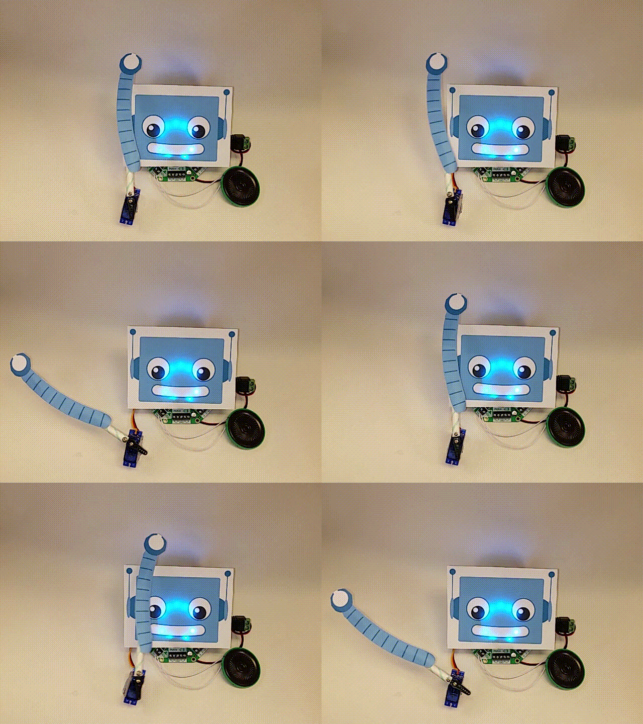
Lately my writing has focused on the new Adafruit Crickit robotics board. This not yet another robotic board (NYARB?). You certainly can make robots that look like the two wheeled bots everybody makes. But it is designed to do so much more. Do you want to use stepper motors and/or servos, check. Add NeoPixel LED lights, check. Add concurrent sound to your project, yes! So you are able to do so much more compared to previous products.
Crickit comes in two versions, one for use with Circuit Playground Express and one for Adafruit Feather processors and boards. Adafruit has hinted of upcoming versions of Crickit for the BBC micro:bit and one for the Raspberry Pi as a HAT.
So, if you'd like to read more of my writing, please visit the Adafruit Learning System and the Adafruit blog.
Sunday, June 19, 2016
Arduinos, New Arduinos, and Pin Header
With a new crop of Arduino compatible boards in "non-traditional" form factors, you may need to consider what type of header pins you want to use on the boards.
Pin header is typically used for:
- Easier connection to a breadboard or to connect wires (electrical)
- Connecting other boards via stacking (mechanical)
Below is the classic Arduino stacking header shield (for prototyping) and that board stacked on an Arduino R3 (right). The shields for the classic Uno R3 are an 8 pin + 10 pin header on top (half-pin space between), and a six pin and 8 pin header opposite (one pin space between, some boards put a nonfunctional header pin between like on the new Arduino Uno WiFi). Boards made since the Arduino Zero have an additional ATN pin on the side closest to the power jack.
![]() |
| Arduino Stacking Shield with female header with long pins (via adafruit.com) |
A shield will need long male pins beneath and the Arduino typically has female pins on top to make the connection. Note the shield above has female pins on top so another shield may be stacked on top of that. If a shield does not need to have another shield stacked on top, you can use plain male header.
![]() |
| Arduino compatible Feather with long female pins for Breadboard, display "shield" on top with male non-stacking pins (via adafruit.com) |
The pictures above demonstrate several things: The Adafruit Feather arduino-compatible board on the left has female header with long male pins to be able to be pressed into a breadboard. The display on top has regular male pins soldered on. The picture on the right shows the two types of header.
Mail order companies (Adafruit, Sparkfun, Farnell, eBay, etc.) sell a lot of different types of header for your making use. Male, female short, female long, single row, double row, and header with 90 degree bends. Male header even comes in extra long for certain applications. Header can come in many widths, the most common when buying header alone is in 40 pin pieces/sticks, although vendors will often sell shorter lengths for specific purposes.
![]() |
| A few different types of header (yes there are many more types) |
Most header is built with a tenth of an inch spacing between pins (0.1" or 2.54 millimeters metric). For some items like XBee radio and some ESP8266 breakouts, they use 2 mm spacing, and some boards may use other spacings. Be careful on guessing the spacing for certain components, boards, displays, etc. Always measure or count twice.
Now on to some of these new Arduino compatible boards coming out. The header pins in the Arduino R3 pictures are nice but they are usually made for 14 on the short side and 18 on the other side. These will not work on some other boards. Here are the header pin counts for some modern boards:
Adafruit Feather has 12 pins on one side, 20 on the other
Arduino.cc MKR1000 has 14 pins on both sides
The Adafruit Huzzah ESP8266 Board has 10 pins on either side (they give you a few extra pins in the header strips)
The NodeMCU ESP8266 board has 15 pins on either side
Making Custom Header Widths
If you have header that is longer than the board you need it for, you can usually cut the header pieces to fit. This may also save money, buying 40 pin sticks and cutting to fit your project.
You should wear eye protection and use caution when preparing to cut header, pieces will fly off!!
Use a good pair of diagonal cutters. Some header, like the male ones, have a groove between pins, making it easy to make a clean cut (often called "breakaway header"). Female header is trickier. Center the cut about in the middle of the next pin after counting out the number you need. Make a straight cut. Be careful as the gold pin will fly out.
![]() |
| Cutting male header (left) and female header (right). Via learn.adafruit.com |
This will leave that side with a bit of a U shape. You can use good cutters to do further trimming. Then use a file to get a nice smooth edge.
Soldering Header
The secret: Use a breadboard or another board with header pins to hold the board to be soldered in place. Have a hot soldering iron and heat each pad+pin and solder.
![]() |
| Using one board to hold pins for another (via learn.adafruit.com) |
With a breadboard, put the pin header in, then the board, then solder. You can also put a piece of male header in a breadboard to secure a female header to solder onto a board (a good use for the extra-long male header). Be sure the board you are soldering is level, once the solder cools, it is hard to level out.
What are your tips for using header in your projects?
Saturday, April 9, 2016
Use Adafruit Feather Wings as MKR1000 Shields
The MKR1000 microcontroller board from arduino.cc is a very new, very powerful board. With the board coming out of beta and now available, the pinout of the board is fixed (compared to the "pinout might change" communicated in the beta).
It will take some time for MKR1000 compatible daughterboards ("shields").
Fortunately, Adafruit makes add-on boards for their new Feather line. Feather comes with several different microcontrollers: AVR 32u4, SAMD21 M0, ESP8266 and some also come integrated with nice radios. Peripheral daughterboards (Adafruit calls "Wings") now available include LEDs, a real-time clock, motor control, relay, servo, and OLED display.
In the absence of MKR1000 shields, you can look to use Feather Wing boards.
Wings are not directly pluggable into headers placed on the MKR1000. The pinouts are different and the M0 processors on the Feather M0 and the MKR1000 are different (SAMD21 vs. SAMW25 respectfully).
To overcome the differences, a sandwich board can be used. This would best be a custom board (think a nice purple PCB with ma1e headers on the bottom, female on the top). with the pins from the bottom switched around to make the top pins fit the Feather Wing pin expectations.
For a proof of concept, I took two Adafruit Proto Feather Wings. They were used to make the wiring changes.
Above, the MKR1000 is the bottom board furthest from the display. It has female headers (with extra long pins for breadboard use also) soldered in (shown below).
The second board, a proto, has two sets of male pins, ones to make with the MKR1000 and male headers pointed up towards the second proto.
The second proto has male headers pointing down to the first and female headers for the Feather Wing daughterboard.
The cross connection may be done with 22 gauge wire. A more old fashioned connection method is to use fine wire wrap wire and connect with a wire wrap tool. See Wikipedia if you're unfamiliar with wire wrapping.
The OLED Feather wing communicates via the I2C bus. To make it work, we need to cross connect the following pins:
It will take some time for MKR1000 compatible daughterboards ("shields").
Fortunately, Adafruit makes add-on boards for their new Feather line. Feather comes with several different microcontrollers: AVR 32u4, SAMD21 M0, ESP8266 and some also come integrated with nice radios. Peripheral daughterboards (Adafruit calls "Wings") now available include LEDs, a real-time clock, motor control, relay, servo, and OLED display.
In the absence of MKR1000 shields, you can look to use Feather Wing boards.
Wings are not directly pluggable into headers placed on the MKR1000. The pinouts are different and the M0 processors on the Feather M0 and the MKR1000 are different (SAMD21 vs. SAMW25 respectfully).
To overcome the differences, a sandwich board can be used. This would best be a custom board (think a nice purple PCB with ma1e headers on the bottom, female on the top). with the pins from the bottom switched around to make the top pins fit the Feather Wing pin expectations.
For a proof of concept, I took two Adafruit Proto Feather Wings. They were used to make the wiring changes.
Above, the MKR1000 is the bottom board furthest from the display. It has female headers (with extra long pins for breadboard use also) soldered in (shown below).
The second board, a proto, has two sets of male pins, ones to make with the MKR1000 and male headers pointed up towards the second proto.
The cross connection may be done with 22 gauge wire. A more old fashioned connection method is to use fine wire wrap wire and connect with a wire wrap tool. See Wikipedia if you're unfamiliar with wire wrapping.
The OLED Feather wing communicates via the I2C bus. To make it work, we need to cross connect the following pins:
- Ground
- Power / 3.3 volts
- I2C data line (SDA)
- I2C clock line (SCL)
- The reset line for the display is connected to Pin 5 on the MKR1000
The code to put test text on the display:
/*
* MKR1000 and Adafruit Feather Wing Code
* Mike Barela http://21stdigitalhome.blogspot.com/
*/
#include <Wire.h>
#include <Adafruit_GFX.h>
#include <Adafruit_SSD1306.h>
#define OLED_RESET 5
Adafruit_SSD1306 display(OLED_RESET);
#if (SSD1306_LCDHEIGHT != 32)
#error("Height incorrect, please fix Adafruit_SSD1306.h!");
#endif
void setup() {
// by default, we'll generate the high voltage from the 3.3v line internally! (neat!)
display.begin(SSD1306_SWITCHCAPVCC, 0x3C); // initialize with the I2C addr 0x3C (for the 128x32)
// Show image buffer on the display hardware.
// Since the buffer is intialized with an Adafruit splashscreen
// internally, this will display the splashscreen.
display.display();
delay(2000);
// Clear the buffer.
display.clearDisplay();
display.setTextSize(1);
display.setTextColor(WHITE);
display.setCursor(0,0);
display.print("Connected to");
display.setCursor(0,16);
display.print("MKR1000!");
display.display();
}
void loop() {
}
Have fun wiring additions to your MKR1000 board including using Adafruit Feather wings.
Subscribe to:
Posts (Atom)


