Monday, December 31, 2012

Arduino Esplora interfaced to an Xbee Radio

Third in a series, I expand on my previous post documenting the Arduino Esplora expansion header and using the hardware and software serial capabilities of the Arduino on the Esplora platform.
For this post, I use a small perfboard and some header to make a plug-in platform for the Xbee project.  To aid prototyping, I use a small breadboard available from most electronic outlets.  You can use the same concept to prototype any circuit you like with the Esplora using the expansion pins I document here.
A perfboard with headers used to anchor it as a base

On the breadboard, I mount an Xbee adapter board (similar to Sparkfun board, also use headers).  As the Xbee operates at 3.3 volts and the Esplora is a 5 volt system at the expansion header, I use a voltage regulator (one from Adafruit was handy but you can make your own 5v to 3v3 circuit, see Igoe Making things Talk, pages 200-201).  Per Igoe, the Xbee data lines are 5 volt tolerant so I interface them directly.

Esplora connections: Pin 10 ground (black), Pin 9 +5 volts (red), Pin 8 Transmit (orange), Pin 7 Receive (green).  +5 goes to the regulator input and the regulator output goes to Xbee pin 1 VCC.  Connect ground to the regulator and XBee grounds.  Note: The receive line pin 7 from Esplora goes to Xbee transmit pin 2, transmit line from Esplora header 8 connects to Xbee receive pin 3.  That's basically it on wiring, not fancy when you know what you are connecting to.
Mounted breadboard with regulator, Xbee carrier and Xbee.  Wiring from the Esplora right header to the breadboard.

For software, I take the lead from my previous post on pin mapping.  The Esplora hardware serial line follows Leonardo conventions.  The Serial function talks to the USB.  The Serial1 function talks to the "D0/D1" hardware serial line we know from programming older Arduinos like the Uno.  These are on Esplora header pins 7 and 8.  Software serial is possible too although the receive pin must be another data line that supports the softwareserial library's interrupt function.  Here I stick with the hardware serial and it is simpler.

I took the Arduino software IDE example sketch "EsploraRemote" and added just the tiniest tweeks to change use of the serial port (USB) to the hardware serial line Serial1.  The code is available as EsploraXbeeRemote at https://github.com/TheKitty/EsploraSerial .  The code is simple but cool - it takes input to either change the buzzer or LED on the Esplora or return Esplora input values.

On radios, I use two Xbee Series 1 radios.  The MY addresses are set to 1 on #1, 2 on #2.  Destinations are set to the other (2 for #1, 1 for #2.  They are also set for serial communications 9600, 8, N, 1.  For Xbee basics, see Making Things Talk or the digi examples website.

Esplora with Xbee and another Xbee talking to it wirelessly
For the transmitter, I use the Foca board I used yesterday - you can use equivalent boards from Adafruit and Sparkfun - they turn a USB port into serial to talk to the Xbee or to talk TTL serial.  You can use any Xbee transmit/receive project to speak to the Esplora - the example just uses a serial terminal to talk to the Xbee which wirelessly sends and receives characters to the Esplora via the other Xbee.  I use the PuTTY serial terminal on Windows - it is available on Mac & Linux or use your favorite serial program.  I set communications to the same as the example program and my Xbees at 9600 baud.  I enabled local echo on the terminal to see what I was typing.

Upload the ExampleXbeeRemote sketch from my Github repository.  Upload the sketch to the Esplora.  Now the USB will only power the unit and we will not use USB to talk to it.  In PuTTY, you type any of the commands listed in the example code headet, for example T440 (which turns the Esplora buzzer on at a frequency of 440Hz).  If it is all connected right and the Bees are set right the annoying buzz will start (use T0 to turn it off).  The Rxxx, Gxxx, and Bxxx commands set the color of the onboard RGB LED.  Very cool.
Screen shot with PuTTY terminal left and Arduino IDE right
With this you can wirelessly communicate with your Esplora, one step closer to making a truly wireless controller (the last step being battery power).  If you use other radios, post your links to your project as a standard serial line will "speak" to nearly any radio link.  Enjoy.

PS Yes the Esplora schematic has a small 3 .3 volt regulator for limited use by one sensor, I did not try to hack into it as it is not readily available and most likely very low current - the 5 volt system has many milliamps for use so a regulator from 5 volt to 3.3 volt (especially an efficient one) is a good solution.  The one I use is a more expensive Adafruit buck converter, overkill at $15 but I had it.  A 78xx or similar regulator and a couple of capacitors like in Making Things Talk works just as well at a lower cost but higher parts count.

Sunday, December 30, 2012

Arduino Esplora Display Preview

Ok, so I am not releasing an LCD for the Arduino Esplora myself.  But in my documentation of the Esplora expansion header (here), I started to notice something from the schematic.
There is no information on the "future display option" other than the released schematic, the press release, and the device info page. The schematic states a 128x160 color display.  The device info states the connector is for "TFT display connector connector for an optional color LCD screen, SD card, or other devices that use the SPI protocol."  It also has the "CD_CS" / "CS-SD" line which seems to confirm a SD card option.

Ok, now where have I seen this . . . browsing the Adafruit displays, I find what I was looking for.  The Adafruit 1.8" display has the exact pinout, resolution, and a micro-SD card slot.


The display is very nice and there is a good library for both text and graphics.  It is not fast (the library could use some speed optimizations) but it is a "shaken out" piece of gear and code.  See the new Adafruit Learning Center tutorial for more information.  Note the tutorial uses an Arduino Uno and not an Esplora.

I note only one anomaly. The Adafruit display pins have pin 1 as a "Lite" backlight pin (which may be pulse-width modulated (PWM) for intensity) with pin 9 as the VCC power pin.  The Esplora schematic has pin 9 as the "BL" (backlight?) and pin1 as +5V.  As both these pins on Esplora are at 5 volts, it would work but the backlight is always on.

Would it not make sense to connect one of the PWM lines of the Esplora's Atmel microcontroller chip to the backlight to provide intensity control?  It would but all these lines are used for onboard items: the RGB LED, the buzzer, the "D13" yellow LED, and the two orange TinkerKit connectors on the top.  None are left for the backlight.

It could be that the Arduino team will release their own branded display.  But then again they could be working a combined effort with Adafruit (like their recent collaboration on the Arduino Micro).

I would say that the Adafruit display will not be the exact display sold for the Esplora - the SD Card slot would rub the left expansion header which is not connected to anything but should serve as a mounting point.  It would then be very likely that the unit to be released will be nearly identical but have the SD card on one of the long sides and the left edge have a 10 pin header to press into the connector providing a good mechanical fit (that is easily taken off if desired given the learning side of this device).

Last note - it is interesting that they decided on their own display rather than the TinkerKit LCD (as they have four TinkerKit connectors up top).  My take is cost as the TinkerKit version has it's own microprocessor, making it a more expensive option and adding bulk.

Follow-up: See my follow-up post on using the Adafruit display (yes it works!)

Esplora Expansion Header Pinouts

As most know, the new Arduino Esplora has an expansion header on the front which is not compatible with previous Arduinos like the Uno, Mega, or Leonardo.  This documents the pins on the header.

As the device encourages hacking (as do all Arduino products, thank you Open Source), I have worked to document the pinouts of the expansion headers.  This is my work and not an official release.  It is based on the officially released schematic, information on the 32U4 chip and electrical and software testing on my part.
The left expansion header (closest to the joystick) appears to not be electrically connected and may only serve to provide a mechanical standoff for the proposed display.  It is the right ten pin header (nearest the 4 buttons) that corresponds to the schematic.  I have designated Pin 1 as the topmost (the top having the USB and white/orange ports) and Pin 10 being at the bottom (the end with the linear sliding resistor).

My interest stems from expanding the capabilities of the Esplora.  Yes it has many sensors and displays, but I may wish to add a sensor.  But more importantly to connect it to the Internet of Things (or to act as a good controller), it should have wireless communication.  So I have connected the Esplora via hard serial and soft serial with good results.

Note: the Esplora has dedicated the pins for another use - we are repurposing the display pins fo this will not work well with both something else and a display connected (you might be able to do something but it is beyond this post).

The hardware serial, Digital Pins 0 and 1 which are Serial Receive and Transmit on classic Arduino Uno etc. map to the Esplora right expansion header pins 7 and 8.  On the Uno they are shared with the USB port but on designs based on the Leonardo like the Esplora, the hardware serial is connected separately.  The hardware serial is addressed as Serial1 for Leonardo style Arduionos (the regular Serial port being the USB).

Software-wise, this means the Serial() function talks to the USB.  The Serial1() function talks to the hardware serial pins.  The SoftwareSerial library works on Leonardo based designs but the receive pin only works on classic I/O pins 8, 9, 10, 11, 14 (MISO), 15 (SCK), and 16 (MOSI) according to a comment in the SoftwareSerial example.  I confirmed the hardware receive pin will not work as the software serial receive (transmit works though).  Here is a wiring diagram for the SoftwareSerial.  Note the ground and 5 volt pins are connected also.

I use a TTL serial to USB device called a Foca from IteadStudios but a FTDI Friend or similar is fine.  It should be 5 volt compliant (as the Esplora is a 5 volt Arduino).  Biggest note: the Esplora Transmit (expansion pin 8) should connect to the receive of the device and the Esplora Receive (hardware is expansion pin 7 for hardware, one of the others like expansion pin 6 for softwareserial).

The software examples for hardware and software serial connection are posted at https://github.com/TheKitty/EsploraSerial

Next up is connecting the serial lines to an Xbee radio.

Thursday, December 27, 2012

Twine Available for Purchase

The Twine sensor is one of the more successful Kickstarter projects completed.  It is a battery-powered wifi sensor node.  It has internal temperature and orientation sensors and can use other sensors purchased separately.

It looks like they have fulfilled Kickstarter orders as they are now available for purchase from the designers website Supermechanical and from Amazon.com.  They are more expensive than the $99 preorder price: $125 from Supermechanical, $140 from Amazon.

My opinion: this could be the basis for a household Internet of Things but the price point has to come down, probably by half at least.  Thoughts?

Gertboard Completed

I posted on October 24th that I had received my Gertboard from Newark, shortly before they discontinued it as a kit.  With the holidays and making my Cylon Pumpkin, I did not have time to build it until December.
It turned out rather well.  Although the parts were not labeled well, I managed to get them all starting with the tiny surface mount components.  I highly suggest a good pair of tweezers like they sell at Adafruit, etc. and a magnifier if you need one.  Gert recommends holding parts in place with a sponge but I prefer Blue Tack meant to hold things on a wall - it's much like silly putty and resists drying out.  It molds to the coponents and keeps them fairly straight.

The headers were a challenge as they came in rows of 18 (singles) and I needed longer to do well so I supplemented with my bench stock.  The long double was short one row and the Arduino JTAG long by one so I suppose it was meant to be cut but cutting a double is not good as they shatter rather than break off with diagnal cutters. 

I have not tested it functionally (still alot going on along with the new Esplora and AlaMode).

I was hoping they would be a bit easier to come by to get the community helping with applications.  For now I suggest Gordon's site for some projects.

The Arduino Esplora is Available from Radio Shack


I have been looking on radioshack.com for days to see if the new Arduino Esplora was available.  Finally on Boxing Day (the day after Christmas) the web site said they were so I drove to a local store and picked one up.  The clerk stated they had them on the shelf for two weeks.


I couldn't find it at first as they were not on the wall with the other Arduinos.  I found out why - the box is about 8 inches (20 cm) long so it is bigger than expected.  The main board is 6" (16 cm) long which is bigger than other Arduinos.

In the box is the joystick cap, the stickers/general pamphlet, but as a surprise a 6 foot USB to USB micro cable!  Nice touch. Note that at the $64.99 price point I would expect a fair amount of value here and the cable helps).

First impressions are good - the buttons on the right are firm, larger and more comfortable than the standard board buttons one finds for microcontroller work. The potentiometer is not too stiff or loose.  Neither is the joystick - not quite as tight as an Xbox 360 but not too loose.

The box states to go to http://arduino.cc/esplora to get started.  You'll need version 1.03 of the Arduino Integrated Development Environment (free download PC/Mac/Linux).  It looks like to use the Arduino Due one uses the experimental 1.5 version - I am unsure if that includes Esplora support.
 
The headers are intended for a small display.  That would be good but what I would really like to see is a way to mount a radio to make this wireless.  Maybe an Xbee?  Any ideas?

Monday, December 17, 2012

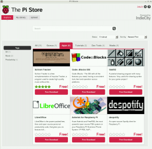
Official Raspberry Pi App Store Open

Today marks the announcement by the Raspberry Pi Foundation of an application (app) store for software, tutorials, and other material for the Raspberry Pi computer.

Currently there are some games, productivity software, and a tutorial and the content is sure to grow exponentially.  Most are free although there is the ability to have software for sale or software for tips.

You can also view the store in a browser at http://store.raspberrypi.com/.


An updated Raspbian Linux image which includes the Pi Store is available from the Raspberry Pi downloads page. Raspbian users can add the Pi Store application to their existing install by typing:

sudo apt-get update && sudo apt-get install pistore


Thursday, December 6, 2012

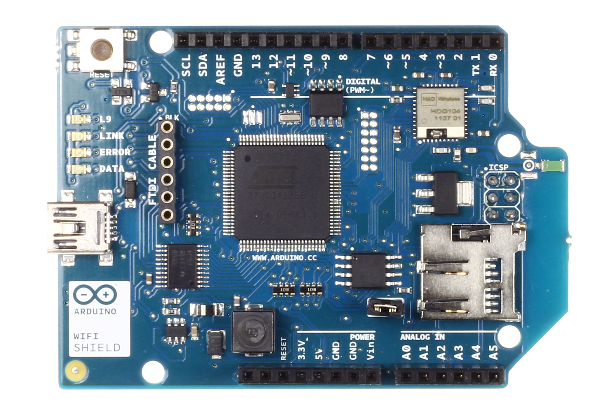
Why are Arduino Wifi shields soooo expensive?

Makers are cheap.  They are frugal and recycle and repurpose but overall they do not want to spend too much money.  So why are the Arduino(tm) shields that connect to wifi so expensive?
The new Arduino wifi is in all rights nearly as powerful as an Arduino Due but costs a whopping $85.  If you have a $30 Arduino, strapping this on is like putting a V8 in a baby Fiat.

Ok, time to turn to the 3rd parties.  A history of boards show high prices also - the Sparkfun WiFly is $70.

Try China?  Itead Studio's board is $60.  The board at Seeed is $60 also.

And all these things are only 802.11 b/g and many require an open router.  Hello??

What to do?  Make one.  I'm thinking the new Electric Imp at $30 and a interface shield at $20 and that's $50.  And the Imp has a Cortex processor on-chip itself.  I think a $30 solution would match the Arduino better but that seems like wishing.

The only other thought I have is some Arduino board with a USB host and can handle a cheap PC type USB wifi stick.  I haven't seen anyone use such with a microcontroller, maybe someone will do that for the Due?

Sunday, December 2, 2012

MicroCenter Maker Parts Expansion

As I had hoped, MicroCenter has increased their stock of electronics and Maker kits.  Parts from Arduino, Sparkfun, Maker Shed and Parallax are included.

They are also selling Arduinos at good prices.  I confirmed they are official models (it was unclear from print and online ads).  Their sale has the Arduino Uno for $17.99 (usually $19.99), Ethernet Shield $29.99, Arduino Ethernet $44.99, Mega $34.99.  The prices on other items appears to follow retail pricing, the clone Osepp Uno is $29.99 as is the Sparkfun Uno.  Sadly no Arduino Due parts spotted.

Now, hopefully Makers get the idea and frequent brick and mortar shops like MicroCenter, Radio Shack, etc. to buy items so they can make a profit.  And there is room to do this - while the online stores are convenient and prices are good, there are times when one is making a project when you want a part NOW, not a week via mail, not a month from China.

There is always the possibility MicroCenter could have a sale post Christmas (and post gift cards, usually around the beginning of the year "end of year sale").