Showing posts with label Trinket. Show all posts

Saturday, January 3, 2015

V-USB

V-USB is some very interesting software by Objective Development that allows many AVR microcontrollers to emulate a USB 1.1 port with only two data lines and 3 resistors.  V-USB can be licensed freely under the GNU General Public License or alternatively under a commercial license.


There's good documentation on their wiki and they link to a number of projects which demonstrate using the software.  Many of the listed projects are using the ATmega8, as the software has been around a number of years.

The Adafruit Trinket and Pro Trinket Arduino compatible boards use V-USB as firmware to download user programs from the Arduino Integrated Development Environment (IDE).  Adafruit has long-standing code in the Arduino IDE to program AVRs using the USBtiny protocol.

Adafruit has also published open source code which demonstrates use of the Trinket as a USB 1.1 human interface device (HID) including mouse and keyboard emulation.  Soon they will publish the same for Pro Trinket.  This is done, again leveraging V-USB code and Adafruit's USB identifiers, to 'bitbang' USB protocols through the data lines connected to the USB connections on the boards (the Trinkets do not have dedicated USB hardware on-board).


Even though the code has been around for awhile, it is still very pertinent for building inexpensive USB interface devices for today's computers. Much of the promise of computer interaction has yet to be realized but is now coming about through the Maker movement and the Internet of Things (IoT).  A large part of achieving this acceleration is low device cost and mass availability.  The Objective Development license scheme and inexpensive AVR processors meet the growing need.

Until such time as anyone can buy $1 chips with a good size ARM core and built-in peripheral functions, designers will still use smaller components and design creativity.

Saturday, October 11, 2014

Comparing Adafruit's Pro Trinket to Trinket and Uno


A few weeks before Getting Started with Adafruit Trinket went to press, Adafruit introduces the Pro Trinket.  It hits a sweet spot in terms of price, performance, and size between the Trinket and the Arduino Uno.  In my comparison chart in the book it was a bit late to add the Pro Trinket so I'll do it here. First, sizing them up visually:
Adafruit Trinket (top), Pro Trinket (middle) and Arduino Uno (bottom) (source: Adafruit)

The Pro Trinket is closer to Trinket's size than an Arduino Uno.   It's smaller than an Arduino Micro or Nano I believe but not by a lot.


Adafruit Trinket

Adafruit Pro Trinket
Arduino Uno

Processor
ATtiny85
Surface Mount
ATmega328P QFN package
ATmega328P
DIP Package
Digital Pins
5
12
14
Analog Pins
3 (shared)
8
6
Pulse Width Modulated Pins
3
6
6
Pin Voltage
3.3 or 5 volts
3.3 or 5 volts
5 Volts
Board Voltage
3.3 or 5 volts
3.3 or 5 volts
5 Volts (3.3 on a pin)
Regulated Current Out
150ma
150ma
800ma
Power via 3.7V LiPo
Possible
Possible
No
USB Chip Onboard
No
No (but has FTDI header)
Yes
USB Plug Type
Mini-USB
Micro-USB
USB-B
USB Programmable
Yes
Yes
Yes
Memory (RAM/EEPROM)
512 / 512 bytes
2048 / 1024 bytes
2048 / 1024 bytes
Flash Memory (free)
8K (5,130 free)
32K (28,672 bytes free)
32K (32K free)
Add-on Shields
No
No
Yes
Board Size
31mm x 15.5 x 5mm
38mm x 18mm x 2mm
75.14 x 53.51 x 15.08mm
Approximate Cost
$6.95
$9.95
$24.95


In terms of Pro Trinket compatibility with Uno, the Pro Trinket does not have digital pins 2 and 7 exposed to pins (they are permanently used for USB, although you could hack into the USB resistors with very fine wire to get them).  Sketches that use pins 2 and 7 may most likely be modifiable to use other pins.

Like some Uno clones, the Pro Trinket adds analog pins 6 and 7 which could be very useful in some applications.

What do you think?  Does the Pro Trinket fit in well in the spectrum of available microcontrollers?  Capability, price, size?  

Trinket / ATtiny85 Internal Temperature and Voltage Sensing


Here is some info that was considered for Getting Started with Adafruit Trinket but was left on the cutting room floor.


The ATtiny85 on Trinket has the ability to sense the voltage applied to it.  This can be useful to determine if a battery is getting a bit too low.  The ATtiny85 also has a built-in temperature sensor.  Some say they don't use it due to a perceived lack of sensitivity.  But the sensor is fairly accurate if calibrated and if a bit of decimal math is used to adjust the temperature values read.

The temperature calibration is discussed in the Atmel document AVR122 - Calibration of the AVR's internal temperature reference at http://www.atmel.com/Images/doc8108.pdf You may need to take some readings and adjust some values in the code to dial-in the most accurate values over a temperature span.

The reading of voltage and temperature requires reading two values using the ATtiny85 analog to digital converter.  Unlike using the analogRead function on external pins, the voltage and temperature are in special areas that are read in similar method to analogRead.  ATtiny85 internal registers are polled to get the values.

Floating point arithmetic is used which adds considerable code overhead to the compiled program.

The sketch below reads the voltage and temperature and outputs the values over a software serial link.  An FTDI cable or FTDI friend connected to Trinket Pin #0 will output the values to a USB port which may be viewed by a terminal emulator.

/* 
 * Trinket / ATtiny85 Temperature and Voltage Measurement
 * Adapted from
 * http://forum.arduino.cc/index.php/topic,26299.0.html,
 * http://www.mikrocontroller.net/topic/315667, and
 * http://goetzes.gmxhome.de/FOSDEM-85.pdf
*/
// Values will be output to Trinket pin #0 via software serial for this example.  
// The library SendOnlySoftwareSerial by Nick Gammon is used to save a pin over
// using the SoftwareSerial library 
// http://gammon.com.au/Arduino/SendOnlySoftwareSerial.zip

#include <SendOnlySoftwareSerial.h>
SendOnlySoftwareSerial Serial(0);       // Output values via serial out on Pin #0

void setup() {
  // Setup the Analog to Digital Converter -  one ADC conversion
  //   is read and discarded

  ADCSRA &= ~(_BV(ADATE) |_BV(ADIE)); // Clear auto trigger and interrupt enable
  ADCSRA |= _BV(ADEN);                // Enable AD and start conversion
  ADMUX = 0xF | _BV( REFS1 );         // ADC4 (Temp Sensor) and Ref voltage = 1.1V;
  delay(100);                         // Settling time min 1 ms, take 100 ms
  getADC();

  Serial.begin(9600);                 // set up serial output
}

void loop() {
  int i;
  int t_celsius; 
  uint8_t vccIndex;
  float rawTemp, rawVcc;
  
  // Measure temperature
  ADCSRA |= _BV(ADEN);           // Enable AD and start conversion
  ADMUX = 0xF | _BV( REFS1 );    // ADC4 (Temp Sensor) and Ref voltage = 1.1V;
  delay(100);                    // Settling time min 1 ms, wait 100 ms

  rawTemp = (float)getADC();     // use next sample as initial average
  for (int i=2; i<2000; i++) {   // calculate running average for 2000 measurements
    rawTemp += ((float)getADC() - rawTemp) / float(i); 
  }  
  ADCSRA &= ~(_BV(ADEN));        // disable ADC  

  // Measure chip voltage (Vcc)
  ADCSRA |= _BV(ADEN);  // Enable ADC
  ADMUX  = 0x0c | _BV(REFS2);    // Use Vcc as voltage reference,
                                 //    bandgap reference as ADC input

  delay(100);                    // Settling time min 1 ms, there is
                                 //    time so wait 100 ms

  rawVcc = (float)getADC();      // use next sample as initial average
  for (int i=2; i<2000; i++) {   // calculate running average for 2000 measurements
    rawVcc += ((float)getADC() - rawVcc) / float(i);
  }
  ADCSRA &= ~(_BV(ADEN));        // disable ADC
  
  rawVcc = 1024 * 1.1f / rawVcc;
  //index 0..13 for vcc 1.7 ... 3.0
  vccIndex = min(max(17,(uint8_t)(rawVcc * 10)),30) - 17;   

  // Temperature compensation using the chip voltage 
  // with 3.0 V VCC is 1 lower than measured with 1.7 V VCC 
  t_celsius = (int)(chipTemp(rawTemp) + (float)vccIndex / 13);  
                                                                                   
  Serial.print("Temp: ");
  Serial.println(t_celsius);
  Serial.print("Vcc: ");
  Serial.println(rawVcc);
}

// Calibration of the temperature sensor has to be changed for your own ATtiny85
// per tech note: http://www.atmel.com/Images/doc8108.pdf
float chipTemp(float raw) {
  const float chipTempOffset = 272.9;           // Your value here, it may vary 
  const float chipTempCoeff = 1.075;            // Your value here, it may vary
  return((raw - chipTempOffset) / chipTempCoeff);
}

// Common code for both sources of an ADC conversion
int getADC() {
  ADCSRA  |=_BV(ADSC);          // Start conversion
  while((ADCSRA & _BV(ADSC)));    // Wait until conversion is finished
  return ADC;
}

The calibration methods used – voltage compensation, along with user testing for values placed in the chipTemp function, can get the accuracy of measurements to within one degree Celsius.

If you wish to keep parts and pin usage to a minimum, reading the temperature with the onboard sensor may provide the capability you need.

In addition, there are several benefits to being able to measure the supply voltage.  If the project is run on battery, Trinket or connected devices could be turned off if power reaches a predetermined lower limit.

Wednesday, October 8, 2014

Select One From Several Inputs

Yesterday, we selected one of many outputs with only 4 pins from an Adafruit Trinket microcontroller.  Here is the mirror project.  Say you have 8 digital data lines in and only few microcontroller lines (Adafruit Trinket only has 5 I/O pins).  You can use a circuit like the one below:


The chip used is the 74XX151 8 input multiplexer.  The binary address of the line you want is sent on Trinket Pins #0, #1, and #2.  Then the data line selected is read in on Trinket Pin #3.  This leaves Pin #4 as an output for serial data or other use.  The code would similar to the sample code below if we only wanted to read the 74151 input pin 3:

void setup() {
   pinMode(0,OUTPUT);
   pinMode(1,OUTPUT);
   pinMode(2,OUTPUT);
   pinMode(3,INPUT);
}

void loop() {
   digitalWrite(0, HIGH);
   digitalWrite(1, HIGH);
   digitalWrite(2, LOW);
   int mydata = digitalRead(3);
}

For a robust program, you'd probably cycle through each 74151 pin address and read the values you want. 

If you only want to multiplex 4 inputs, you can use a smaller multiplexer or just ground S2 low, freeing Trinket Pin #2.

Tuesday, October 7, 2014

Triggering Ten Pins with Four Outputs

A common issue in microcontrollers: what do you do when the pins on your controller do not match well with the outputs to your controlled items?  This is something I wanted to write about in Getting Started with Adafruit Trinket but I was over on page count as it was, so I'll post it here for you.

What the designer may not normally think about is using TTL logic chips.  Often called 74 series after the original numbering by Texas Instruments, there are hundreds of pre-existing integrated circuits to help make outstanding projects.  A number of years back it was one of the only ways to make circuits.... anyway...

Take Trinket.  There are only 5 I/O pins.  What if you want to use some sensor or serial input to output one of ten outputs (say to the delicious Adafruit Audio FX Sound Board that just came out).  You could be satisfied triggering only 4 of the sound board's trigger pins. But we want more!

So 4 binary digits can actually represent 16 different outputs (0 to 15 or 0 to F in hexadecimal).  Would one create a bunch of 7400 series logic (AND, OR, NAND) gates to change a number to one of several outputs?  You could, but it takes alot of gates;

Gates to decode 4 digital signals to 10 outputs
There is a way to reduce this down to one 16-pin DIP chip - use the 7442 BCD to decimal decoder IC.  All the logic above is already pre-wired into one easy to use chip!  So how would we wire Trinket to use the 7442 to the Adafruit Audio FX Sound Board which wants one of many pins to trigger a file to be played?  See the wiring diagram below:


If you set the right 4 bit number on Trinket pins 0 to 3, it will trigger one of ten outputs to the sound board, triggering the playing of up to ten sounds.  The code to trigger output 5 would include:

void setup() {
   pinMode(0,OUTPUT);
   pinMode(1,OUTPUT);
   pinMode(2,OUTPUT);
   pinMode(3,OUTPUT);
}

void loop() {
   digitalWrite(0, HIGH);
   digitalWrite(1, LOW);
   digitalWrite(2, HIGH);
   digitalWrite(3, LOW);
}

If you hooked a transmitter like an Adafruit Bluefruit or other receiver to Trinket Pin #4, you could use Trinket to set the right combination of 4 states on Pins #0-3 to trigger the right sound output. (Note: if you connect to pins #3 and #4 on Trinket, be sure to disconnect these when you use the USB programming connection, then reconnect when programming is done). And the Sound Board can hold alot of WAV file sound compared to a tiny bit on Trinket itself.

Note the data sheet I link to is the 74HC42.  The letters in the middle (if any) designate different types of logic (some improvements have been made in these chips over the years.  I'm partial to LS logic, although nearly any will do that I'm aware of, just be sure if you use 5 volt logic you are consistent).

You can see the usefulness of older chips in making the most of newer microcontrollers and modules.  With a bit of study of the 74 series chips, I'm sure you can find some that will help you in projects on your drawing board.

Saturday, October 4, 2014

Announced Today: Arduino Gemma

During his October 3rd presentation at Maker Faire Rome, Massimo Banzi gave a preview of a new collaboration and a new board: Adafruit Gemma becomes officially Arduino Gemma, a tiny but powerful wearable microcontroller board in a 27mm diameter package.
Powered by an Attiny85 and programmable with the Arduino IDE over USB, anyone will be able to easily create wearable projects with all the advantages of being part of the Arduino family. The board will be default-supported in the Arduino IDE, equipped with an on/off switch and a microUSB connector.
gemmapresentatio2
gemmapresentation


The Attiny85 is a great processor because despite being so small, it has 8K of flash and 5 I/O pins, including analog inputs and PWM ‘analog’ outputs. It was designed with a USB bootloader so you can plug it into any computer and reprogram it over a USB port (it uses 2 of the 5 I/O pins, leaving you with 3). Ideal for small & simple projects sewn with conductive thread, the Arduino Gemma fits the needs of most of entry-level wearable creations including reading sensors and driving addressable LED pixels.

After the fruitful joint effort developing Arduino Micro, once more the Arduino Gemma has been developed in collaboration with Adafruit Industries, one of the main leaders of the Maker movement. Technical specifications:
Microcontroller: ATtiny85
Operating Voltage: 3.3V
Input Voltage (recommended): 4-16V via battery port
Input Voltage (limits): 3-18V
Digital I/O Pins: 3
PWM Channels: 2
Analog Input Channels: 1
DC Current per I/O Pin: 40 mA
DC Current for 3.3V Pin: 150 mA
Flash Memory: 8 KB (ATtiny85) of which 2.5 KB used by bootloader
SRAM: 0.5 KB (ATtiny85)
EEPROM: 0.5 KB (ATtiny85)
Clock Speed: 8 MHz
MicroUSB for USB Bootloader
JST 2-PH for external battery

Wow, major announcement.  Default support for the ATtiny85 on Gemma would be a big help, to include Adafruit Trinket (the original, not Pro).

What will Arduino do next?

Wednesday, October 1, 2014

Getting Back to Blogging after Publishing the Book

As blog readers are probably aware, I have been working on a new book for Maker Media called Getting Started with Adafruit Trinket.  It's been a labor of, well, work.  It has been a great experience but I'm ready to get back to a wider array of projects.

The book details use of the Trinket - an ATtiny85 breakout board from Adafruit Industries.


Here is the back and front cover.  It has changed over the last few months, the title a bit, the cover definitely new and a departure from many Make books.  Another departure is color - the inside is printed in color vs. black and white for most Getting Started books.  This allows you to really see the wiring and the projects.

The source code and the illustrative pictures have been posted on GitHub at https://github.com/trinketbook/GettingStartedWithTrinket

If you would like to see the Adafruit "Ask an Engineer" webcast in which I join Limor "Ladyada" Fried and Phil Torrone talk about many things including the book, here is the video:


Please excuse my actions and the bags under my eyes!  I had been awake for like 22 hours at that point and I need my beauty sleep after 16!  Curse transatlantic flights!

The book is available in final release via ebook in  ePub, Mobi, and/or PDF formats from O'Reilly at http://shop.oreilly.com/product/0636920031598.do or preorder the paperback from Amazon.com.  It should be out by mid-October!

Monday, April 21, 2014

Book Announcement: Getting Started with Trinket

Now you may officially know why I have not posted much in the last few months.  From September through December, I was writing tutorials on http://learn.adafruit.com as previously discussed.  I was contacted by Maker Media who asked for a book on the Adafruit Trinket microcontroller.  How could I refuse?  So I have been writing and writing some more.  Today Amazon now has it for preorder:

Getting Started with Adafruit Trinket


The price will probably be a bit less than those listed as it will probably be edited down a bit more.

A prerelease hardcopy will be out for Maker Faire New York, September 20 & 21st.

More information and it develops.  Thank you to my viewers for your support of my projects.  Mike

Sunday, November 3, 2013

Sensing Switches on an Analog Input, Including Multiple Key Presses

Many microcontroller projects quickly run out of pins when adding functionality.  The methodology used to continue to add functionality is to use expansion chips or share pins.  Many methods implement an approach that will register individual switches.  This article shows a method detecting single or multiple key presses.

One method recently written about at http://tronixstuff.com/2011/01/11/tutorial-using-analog-input-for-multiple-buttons/ uses a well known method of using one analog pin to register different values for different key presses.

This method is also used on various "LCD Shields" used to add buttons to an LCD display on Arduinos.

While these methods work well, they will not correctly register two buttons pressed at the same time.  For the first picture, if the far right button is pressed, the line is grounded and no further buttons will register.  Same for the second picture with the "RIGTH" button.  The reason is the button shorts out parts of the resistor "ladder".  Again, these work, but only give the lowest value to the analog pin.

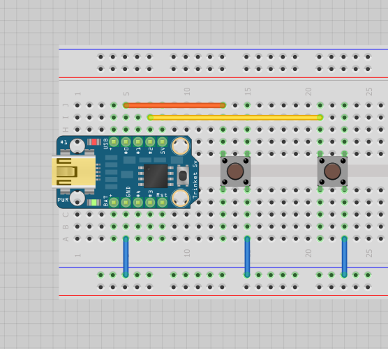
For my next project, an alarm, I need to be able to differentiate between pins including multiple "buttons" at the same time.  The following is a schematic of what I will use to differentiate between 3 inputs:

The R4 pullup resistor can be the same as the internal pull-up on microcontrollers like the Arduino, enabled via 
pinMode(analogpin, INPUT_PULLUP); 
or 
pinMode(analogpin, INPUT); 
digitalWrite(analogpin, HIGH);  // set pullup on analog pin while the pin is an input.

On Arduinos like Uno, analogpin can be A0 through A5.  For ATtiny based boards like Adafruit Trinket and Gemma, you must use numbers 1 to 3 for the analog pin (GPIO #2 is A1, GPIO #3 is A3, GPIO #4 is A2 only on Trinket and not Gemma).  Note the pullup does change the range of the AnalogRead.  See http://arduino.cc/en/Tutorial/AnalogInputPins for more information.

My application uses an Adafruit 5 volt Trinket.  In the schematic of the Trinket board, pin GPIO #3 (Analog 3), already has a 1.5 K ohm pullup to use USB, so no additional pullup resistor is required for use, a bonus.

For mapping values, you can read the analog measurement as various switch states are changed (your values may differ depending on resistor changes, pull-up values, etc.  You should take measurements on your own setup):

Switches   Value
Nothing    647
1 closed   397
2 closed   537
3 closed   576
1 and 2    320
1 and 3    342
2 and 3    457
All closed 283 

This works by using changing resistors in parallel along with R4 in series.  So if Switches 1 and 2 are closed, the resistance is (R1*R2)/(R1+R2) + R4.  See Wikipedia for a detailed explanation of resistor combinations.  This is also why the resistor values on the switches must be different - you are looking for unique resistances for each combination.  If you use the same values on the switches, the same analog reading will register for each key press.

The values do not have to be the same as the ones I used.  Avoid too small values to limit current to the analog pin.  Avoid values in the Megohm range as being too close to an open.  Values should not be too close or too far from each other.  I suggest you wire the circuit up and measure the values. You want probably 10 or more analog value steps between each registered combination.  

Sometimes due to conditions, the same read value will not always come up but be a close value.  This is called jitter and for my project it was about 2, so when you compare values you want to check like this:

const int jitter = 3;
int readvalue;
int switchone = 397; // from table above for my circuit

readvalue=analogRead(analogpin);  // use your pin number

if(readvalue >= (switchone-jitter) && readvalue <= (switchone+jitter) ) {
    Serial.println("Switch one is closed");
}

Replace the if statement with a switch case statement for multiple buttons.

So for a project where you may have multiple key presses, you can sense them on one analog input by placing switches in parallel with differing resistors.


Sunday, September 22, 2013

Summer Lull and Where New Projects Are Being Posted

Summer has been rather busy around here.  With warm weather comes home improvement and three fair sized projects (deck, plumbing, foundation leak).

But I've still had time for electronic projects.  I received my Adafruit Trinket ATTiny85 based board and I was off connecting circuits.  This was a challenge, as many Arduino libraries do not work out of the box as the Tiny has fewer onboard hardware resources and limited memory.   So I started some posts on my progress, not here on the blog but on Google+.   It was faster.

Then I got "the e-mail".  Adafruit sent me a message stating they liked the work I had done on Trinket and asked if I wanted to write some tutorials.  Of course!  After formally asking work to ensure I had the ethics issues taken care of, I've started some articles, two of which have been posted.  My articles will appear in a group on this page.


Exciting, definitely.  So for fans of my open source posts, for now I suggest looking on the Adafruit Learning System for guides, mine will be there.