What is the Adafruit Learning System? It's 1500+ free tutorials on making. With the best writers on making, electronics, and open source, the Adafruit Learning System is the place to look for inspiration for your next project.
Of course I have a good deal of writing on the Circuit Playground Express board - it's the easiest way to start interacting with electronics and making.
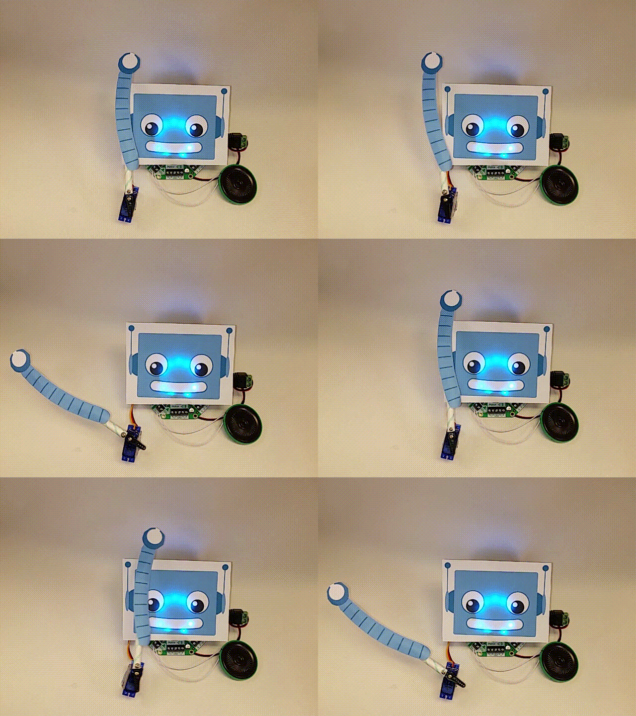
Lately my writing has focused on the new Adafruit Crickit robotics board. This not yet another robotic board (NYARB?). You certainly can make robots that look like the two wheeled bots everybody makes. But it is designed to do so much more. Do you want to use stepper motors and/or servos, check. Add NeoPixel LED lights, check. Add concurrent sound to your project, yes! So you are able to do so much more compared to previous products.
I recently bought a Pi Supply PaPiRus Zero ePaper/eInk pHAT v1.2 from Adafruit. I went to the Pi Supply website but the documentation was not so good. And even going through the PaPiRus GitHub instructions, I had issues with my board not working right that required tech support from Pi Supply. I finally got it to work, so I'll list my success for others.
If you have any other driver board that is not the Pi Supply PaPiRus Zero ePaper pHAT v1.2, you'll want to look at the end of this post for pointers to resources that might apply.
Measure the Display Size
The display and board Adafruit currently sells is the 2.0 inch board. I had originally thought it was the small 1.44 as that is what the Pi Supply site had on it but I hadn't measured the display (Adafruit correctly says 2.0"). Here is the diagonal display measurement you should make. If you don't have an inch ruler, divide the number of centimeters by 2.54 to get inches. The PaPiRus Zero should have a 2.0 inch display.
Measure your display from far corner to far corner diagonally. This one is 2.0 inches. Ruler by Adafruit.
If your display measures different from 2.0 inches, your settings and configuration may need changing.
Jumper Setting
It is important to set the jumper across the pins on connector CN2 correctly so that the board handles your display correctly. If this is set wrong you'll get unwanted lines or behavior of the display.
Jumper pins 2 and 3 for a 1.44" or 2.0" display
Jumper pins 1 and 2 for a 2.7" display
Take the jumper off (or just have it on pin 1 and off 2 and 3) for a 1.9" or 2.6" display
The board Adafruit ships is the 2.0 inch. So you want the jumper looking like this:
Board to Display Connection
To open the connector at the back of the PaPiRus board you need to lift the dark brown clip on CN1 by using your fingernail to grab the dark brown part on the end of the board and rotating up gently allow it to rotate over its hinges until it is perpendicular to the board. The brown part clips on the beige one so it is normal for it to give a slight resistance when opening the connector. The pictures are copyright so you'll have to look at them on the link below:
With the connector open, slide the cable on the beige part of the connector and gently push it so that it reaches underneath the brown clip. Make sure that the cable is inserted evenly so that when the clip is rotate back into the closed position the two dots shown in the picture are parallel with the connector.
This is one of the main causes of the screen not operating correctly so make sure you pay particular care when plugging the screen into the ribbon connector CN1.
Once the cable is in the correct position, rotate the brown clip into the closed position. You will notice that it will provide some resistance but this is absolutely normal.
Take the two bits of sticky take and put them so they hold the display down. Be careful, removing the tape later is very hard and not recommended.
You have two squares of tape to hold the display down.
Connect the two plastic standoffs to the display pHat board (be careful to not damage the display).
At this point, your Pi Zero must have the GPIO pins added. You need to order this separately from the Pi Zero and the display pHat. At Adafruit it is part number 3335, at Pi Supply it is here.
You can follow this Instructable on soldering the header onto your Pi Zero. You will need solder, a soldering iron with a fine tip, some tape or Blu Tack to hold the header while soldering and some patience.
When you have the header soldered onto the Pi Zero, you can connect the display pHat board to the Pi Zero GPIO header to make a circuit board sandwich. Ensure the pins of the Pi line up with the pHat socket. Use the last two plastic screws to secure the Pi to the standoffs. The boards should be well connected now.
Software Installation
Install Raspbian on a micro SD card
If you don't have a micro SD card set up with the Raspbian Linux operating system, see this Adafruit tutorial on how to get it and set it up. Other operating systems like Arch Linux are not supported by the software driver, if you don't use Raspbian you're on your own.
You'll need to do some more set up for the display below.
Connect a display and keyboard to your Pi Zero (Adafruit and Pi Supply, among other shops, have adapter cables for mini-USB to USB/VGA and micro USB to USB). For advanced users, you can log in via another computer via the SSH protocol with a USB to micro USB cable, tutorial here.
Log into your Pi Zero, the default is username Pi, password Raspberry. Best to change the password at some point, remember the password if you do change it.
Enabling SPI and I2C interfaces on Raspberry Pi
Before using PaPiRus, you need to enable the SPI and the I2C interfaces which talk between the Pi and the display. You can enable the SPI by typing sudo raspi-config at the command line and then selecting Interfacing options > SPI and then selecting Enable. Without exiting the tool still in Interfacing options > I2C and then selecting Enable.
Setup PaPiRus Software
Run this line and PaPiRus will be setup and installed
curl -sSL https://goo.gl/i1Imel | sudo bash
You'll see alot of text scroll by as the software installs, that's normal.
All of the software will install in a directory named PaPiRus
Commands to Run
Select your screen size for the 2.0" display
sudo papirus-set 2.0
For other sizes, it works with papirus-set [1.44 | 1.9 | 2.0 | 2.6 | 2.7 ]
Write data to the screen
papirus-write "Some text to write"
Clear the screen
papirus-clear Draw image on the screen
papirus-draw /path/to/image -t [resize | crop]
The PaPiRus can only display Bitmap images (.BMP) in black and white (1 bit colour). If you pass an image to PaPiRus that is not a 1 Bit Bitmap, it will automatically be converted to this by the software. However, for best results and higher image quality we would recommend that you convert the image to a 1 Bit Bitmap before pushing to the PaPiRus screen using GIMP or Photoshop or similar photo editing tools.
The default bitmap sizes for the different displays:
1.44" 128 x 96
1.9" 144 x 128 2.0" 200 x 96 - The Raspberry Pi Zero kit at Adafruit
2.6" 232 x 128
2.7" 264 x 176
Good response today as I posted on social media the picture below - the Adafruit Circuit Playground low cost experimenter board and a 3xAAA battery pack fit well in a Pringles potato chip (crisp) can:
So I have been playing with the accelerometer sensor in the Circuit Playground. You can do some sophisticated things with an accelerometer. Let's see what I did with the can.
Use some Blu-Tack, silly putty, clay, etc. to attach Circuit Playground to the battery pack. Just be sure the adhesive is not permanent and non-conductive. Plug the battery pack into the Circuit Playground and turn it on. Slide it into the can, it'll fit fine and not slide around (yay!).
First, I'll light up one Circuit Playground LED NeoPixel green. Program Circuit Playground with the first sketch below (which turns on NeoPixel #2). Then I put the Circuit Playground into the can so it is fixed to the bottom. Then I roll the can. The LED will do loop-de-loops in circles similar to the following diagram:
And in the dark it looks like this:
Now, say I want the LED to always be at the top of the can. I can try to time the lighting of the LED to the rate at which I spin the can but I'm not a good can roller and it would get all messy.
So I use the accelerometer on Circuit Playground to tell which way is "up" as the can rolls at any speed. An accelerometer measures both the pull of gravity on the sensor and changes in movement. If you roll Circuit Playground like we did above, there will be changes in the X and Y directions (the Z axis doesn't change rolling the can as I have mounted it). See the board for which ways are
Is keeping the LED lit at the top of the ring as the can rolls even possible? Yes. It takes some math though. You can read the acceleration values as the can rolls in rolling distance and as the can presses on the ground due to gravity. Kind of like the figure below from the Wikipedia article Circular Motion under the non-uniform heading
Program the Circuit Playground with the second sketch below. The code boils down to finding the angle between the x and y values of the accelerometer reading, calculating an angle. That angle is used to determine which of the 10 NeoPixels on Circuit Playground needs to be lit to remain at the top of the ring. That method allows for the rate of rolling the can (shown as v in the diagram) to vary and the rate of rolling does not matter (except a tiny bit for code speed).
The LED at the top of the circle is lit at all times. It looks like this in the Pringles can:
So with little more than an empty can, Circuit Playground and a battery pack, we've used a bit of sensing and programming to make something do what intuitively it shouldn't do. This behavior is actually VERY useful and can be used to make bigger and better things.
And that's the beauty of Circuit Playground. You can do so much with the capabilities onboard and you don't need to buy a lot of stuff to make it do great things, just look in the cupboard perhaps.
Code
Code for one LED:
// CPoneLED
//
// Set for Circuit Playground to display one LED Continually
// CPaccelerometerLED // // Set the LED at the "top" of the Circuit Playground NeoPixel ring // no matter the x or y orientation (like when rolling) // // Mike Barela August 23, 2016 MIT License #include <Adafruit_CircuitPlayground.h> #define NUMBER_OF_LEDS_ON_RING 10 const int brightness = 16; int ledPosition, currentQueueSize; void setup() { CircuitPlayground.begin(); CircuitPlayground.setBrightness(brightness); CircuitPlayground.clearPixels(); } int led, previousLed=0; float x, y, nx, ny, angle; void loop(){ x = CircuitPlayground.motionX(); // Read the accelerometer X & Y y = CircuitPlayground.motionY(); nx = x / 10.0; // Scale to -1 to +1 in ny = y / 10.0; // both directions angle = atan((ny/nx)) * 180 / 3.14; // get the angle from "down" if(angle > 0.0){ // As Arctangent won't give the angle over the if(nx < 0.0) // entire 360 degrees, adjust depending angle += 180; // on direction the acceleration was going } else { if(ny > 0.0) angle += 180; else angle += 360; } if(angle == 360.0) angle = 0; // We have 10 LEDs in a circle - need to light the right one led = circularize(angle / (360 / NUMBER_OF_LEDS_ON_RING)); // make led movement smooth if(previousLed == led){ // no movement, just reloop // nothing to do } else if (counterClockwiseDistanceBetweenLeds(previousLed, led) <= 8) { led = circularize(previousLed + 1); // change detected, makeLightShow(previousLed, led); // change LED previousLed = led; } else { led = circularize(previousLed - 1); makeLightShow(previousLed, led); previousLed = led; } delay(25); } void makeLightShow(int previousLed, int led) { // light NeoPixel CircuitPlayground.strip.setPixelColor(previousLed,0,0,0); CircuitPlayground.strip.setPixelColor(led, 0, brightness, 0); CircuitPlayground.strip.show(); } int circularize(int pos){ // if a position gets to be < 0 or > 9 if(pos >= NUMBER_OF_LEDS_ON_RING) return(pos - NUMBER_OF_LEDS_ON_RING); else if(pos < 0) return(pos + NUMBER_OF_LEDS_ON_RING); else return(pos); } int counterClockwiseDistanceBetweenLeds(int prevPos, int nextPos){ int distance; distance = nextPos - prevPos; if(distance < 0) distance += NUMBER_OF_LEDS_ON_RING; return(distance); } An exercise for the student / magician is to make one sketch, it acts one way with the slide switch at the + position, another when switched to -. Code heavily modified from https://petervojtek.github.io/diy/2015/01/24/neopixel-gravitation.html, the page gives some good info on the subject also.
My latest work was posted yesterday on the Adafruit Learning System. Their new Circuit Playground experimenting board has alot of uses. I explored using the onboard speaker to make sound and music. It progresses using the onboard light, temperature, and motion sensors. Finally it is programmed to play a Simon lights and sound game using the capacitive touch pads. It's a very flexible board.
Unless you've been stuck upgrading all your computers to Windows 10 before the deadline of July 29th, you may have heard that the 2000's sensation Pokemon has been reborn in a new augmented reality game Pokemon Go.
Poke Balls are the red and white spheres that a person uses to catch Pokemon.
Adafruit's NeoPixel light rings can be set to half red and half white to simulate a Poke Ball.
The code below has been set for the 10 pixels on Circuit Playground. The code can be used on any Adafruit NeoPixel ring with quick changes to the constants at the start.
Have fun!
// CPpokeball Paints your Adafruit NeoPixel ring in Poke Ball colors // // Set for Circuit Playground but works for all Adafruit NeoPixel Rings with // correct pixel pin number and pixel count // // Mike Barela July 23, 2016 MIT License #include <Adafruit_NeoPixel.h> const int pixelPin = 17; // NeoPixel pin number for Circuit Playground const int pixelCount = 10; // Number of Neopixels (10 for Circuit Playground) const int pixelBrightness = 30; // 0 to 255 Adafruit_NeoPixel strip = Adafruit_NeoPixel(pixelCount, pixelPin, NEO_GRB + NEO_KHZ800); uint32_t red = strip.Color(255, 0, 0); uint32_t white = strip.Color(255, 255, 255); uint32_t black = strip.Color(0, 0, 0); void setup() { // this resets all the neopixels to an off state strip.begin(); strip.show(); strip.setBrightness(pixelBrightness); } void loop() { setPixelsPokeBall(); // set Pokeball colors delay(5000); // delay 5 deconds for( int8_t j=1; j<=5; j++) { // blink Pokeball colors 5 times setPixelsOff(); delay(700); setPixelsPokeBall(); delay(700); } delay(2000); // wait a bit and start again } void setPixelsOff(void) { for(int8_t i=0; i<=9; i++) { strip.setPixelColor(i, black); } strip.show(); } void setPixelsPokeBall(void) { for(int8_t i=0; i<(pixelCount/2); i++) { strip.setPixelColor(i, red); } for(int8_t i=(pixelCount/2); i<pixelCount; i++) { strip.setPixelColor(i, white); } strip.show(); }
The MKR1000 microcontroller board from arduino.cc is a very new, very powerful board. With the board coming out of beta and now available, the pinout of the board is fixed (compared to the "pinout might change" communicated in the beta).
It will take some time for MKR1000 compatible daughterboards ("shields").
Fortunately, Adafruit makes add-on boards for their new Feather line. Feather comes with several different microcontrollers: AVR 32u4, SAMD21 M0, ESP8266 and some also come integrated with nice radios. Peripheral daughterboards (Adafruit calls "Wings") now available include LEDs, a real-time clock, motor control, relay, servo, and OLED display.
In the absence of MKR1000 shields, you can look to use Feather Wing boards.
Wings are not directly pluggable into headers placed on the MKR1000. The pinouts are different and the M0 processors on the Feather M0 and the MKR1000 are different (SAMD21 vs. SAMW25 respectfully).
To overcome the differences, a sandwich board can be used. This would best be a custom board (think a nice purple PCB with ma1e headers on the bottom, female on the top). with the pins from the bottom switched around to make the top pins fit the Feather Wing pin expectations.
For a proof of concept, I took two Adafruit Proto Feather Wings. They were used to make the wiring changes.
Above, the MKR1000 is the bottom board furthest from the display. It has female headers (with extra long pins for breadboard use also) soldered in (shown below).
The second board, a proto, has two sets of male pins, ones to make with the MKR1000 and male headers pointed up towards the second proto.
The second proto has male headers pointing down to the first and female headers for the Feather Wing daughterboard.
The cross connection may be done with 22 gauge wire. A more old fashioned connection method is to use fine wire wrap wire and connect with a wire wrap tool. See Wikipedia if you're unfamiliar with wire wrapping.
The OLED Feather wing communicates via the I2C bus. To make it work, we need to cross connect the following pins:
Ground
Power / 3.3 volts
I2C data line (SDA)
I2C clock line (SCL)
The reset line for the display is connected to Pin 5 on the MKR1000
The code to put test text on the display:
/*
* MKR1000 and Adafruit Feather Wing Code
* Mike Barela http://21stdigitalhome.blogspot.com/
Arduino Day gives folks the opportunity to showcase their work with these easy to use microcontrollers. Today's project is something I've wanted for awhile: an Internet connected air quality display. Folks looking to go outside want a quick glance look at how the air quality is that day. This includes runners, those with breathing problems, and young children.
Components
There are several blocks to the project, both hardware and software:
Arduino Uno Microcontroller
Arduino Ethernet Shield
Adafruit LCD Display (select one that does not require hardware SPI that conflicts with the select line).
The ethernet shield is connected to your home network. The software sketch ensures all the pieces are communicating, then it obtains the air quality based on the latitude and longitude of the project. This is available in the United States for free from the U.S. Environmental Protection Agency (EPA) via their free AirNow API. In other countries, there are some data service providers, the code would need to be written to read the other service's API and data, see the list at http://www.airnow.gov/index.cfm?action=airnow.international
Once the data is collected, the specific data desired is parsed out of the HTTP code and API output. Then the data is written to an LCD display. A color display is important as the U.S. EPA has specific colors for specific air quality levels:
AQI Numbers
AQI Category (Descriptor)
AQI Color
Hexadecimal Color Value
Category Number
0 - 50
Good
Green
(00e400)
1
51 - 100
Moderate
Yellow
(ffff00)
2
101 - 150
Unhealthy for Sensitive Groups
Orange
(ff7e00)
3
151 - 200
Unhealthy
Red
(ff0000)
4
201 - 300
Very Unhealthy
Purple
(99004c)
5
301 - 500
Hazardous
Maroon
(7e0023)
6
So the display should be clear seen from a distance using the EPA colors what the status is. For a 24 bit (3 byte RGB) color display, the color values specified above can be sent. I tried to use two other displays: a large touchscreen (conflicted with the Ethernet SPI control) and a display shield (I probably have a wiring issue with it) so I jumped to a trusty display I have written about used with the Arduino Esplora. The problem is it is discontinued and it is only 16 bit color. SO I had to tweak the Adafruit driver library code to compile under the Arduino IDE Version 1.6.x and to use 16 bit colors. I have tried to get similar colors but I suggest you select colors that you find are closest to the colors above. If you can find a color picker for 16 bits, place a comment below.
You will need to get an API key from www.airnow.gov. The key is free but you need to sign up. Replace my key in the code (please!) with your own.
Code
I'll admit the code is not as elegant as that in many of my Adafruit tutorials. I had to change displays late in the project. And I did not use a GPS shield to keep the project simple but that does not help in portability. Also I've selected the US service with a link to other countries' air quality services. Each will probably have their own data format which will require the correct code to parse the data, that has not been done here except for the US formatting.
/*************************************************** Air Quality Monitoring Uses the Arduino Uno, Ethernet Shield, and Adafruit 1.8" display shield http://www.adafruit.com/products/802 Check out the links above for our tutorials and wiring diagrams Adafruit invests time and resources providing this open source code, please support Adafruit and open-source hardware by purchasing products from Adafruit! Based on code written by Limor Fried/Ladyada for Adafruit Industries. MIT license, all text above must be included in any redistribution ****************************************************/ #include <Ethernet.h> #include <SPI.h> #include <Adafruit_GFX.h> // Core graphics library #include <Adafruit_HX8340B.h> // Display Color definitions #defineBLACK 0x0000 #defineBLUE 0x001F #defineRED 0xF800 #defineGREEN 0x07E0 #define CYAN 0x07FF #define MAGENTA 0xF81F #define YELLOW 0xFFE0 #define WHITE 0xFFFF #define ORANGE 0xF500 byte mac[] = { 0xDE, 0xAD, 0xBE, 0xEF, 0xFE, 0xED }; // Ethernet shield MAC address char server[] = "www.airnowapi.org"; IPAddress ip(192, 168, 0, 178); // select for your home network - it will try DHCP first though EthernetClient client; uint8_t lineCount = 0; // TFT display will NOT use hardware SPI due to the SPI of the Ethernet shield // SO other pins are used. This makes the display a bit slow #define SD_CS 4 // Chip select line for SD card #define TFT_CS 9 // Chip select line for TFT display #define TFT_SCLK 6 // set these to be whatever pins you like! #define TFT_MOSI 7 // set these to be whatever pins you like! #define TFT_RST 8 // Reset line for TFT (0 = reset on Arduino reset) Adafruit_HX8340B tft(TFT_MOSI, TFT_SCLK, TFT_RST, TFT_CS); void setup(void) {
Serial.begin(115200); Serial.println(F("Air Quality Monitor")); if (Ethernet.begin(mac) == 0) { Serial.println("Failed to configure Ethernet using DHCP"); // no point in carrying on, so do nothing forevermore: // try to congifure using IP address instead of DHCP: Ethernet.begin(mac, ip); } // Give the Ethernet shield a second to initialize: delay(1000); Serial.println("Ethernet connecting..."); // if you get a connection, report back via serial: if (client.connect(server, 80)) { Serial.println("Ethernet connected"); // Make a HTTP request // Change the latitude/longitude for your location // You need your own API key from www.airnow.org pasted into the string below // If you will go mobile, get lat/long from GPS or from your outward IP address // from a service like http://www.freegeoip.org/ client.println("GET /aq/forecast/latLong/?format=text/csv&latitude=38.8&longitude=-77.3&distance=25&API_KEY=FE62B688-EE27-4214-8BD8-9903E1AC5881 HTTP/1.1"); client.println("Host: www.airnowapi.org"); client.println("Connection: close"); client.println(); } else { // If you didn't get a connection to the server: Serial.println("Ethernet connection failed"); } client.setTimeout(1000); tft.begin(); // Initialize TFT tft.setRotation(1); // Landscape display } void loop() { char buffer[160]; // The HTTP read buffer - the maximum line returned by the API is 158 chars char partInfo[4][10]; // The air quality values are placed in 4 strings of length 10 characters uint8_t tokenCount, valueCount; char *bufValue; char *bufPtr; if (client.available()) { byte numChar = client.readBytesUntil((char)0x0a,buffer,159); // Read until a line feed character buffer[numChar]='\0'; lineCount = lineCount + 1; if(lineCount == 11) { // Parse first record Serial.print("-> "); Serial.println(buffer); tokenCount=0; valueCount=0; bufPtr = strtok(buffer,","); while(bufPtr != NULL && valueCount < 10) { if(valueCount > 5) { strcpy(partInfo[tokenCount], bufPtr+1); tokenCount++; } bufPtr = strtok(NULL,","); valueCount++; } for( uint8_t i=0; i<4; i++) { for( uint8_t j=0; j<10; j++) { if(partInfo[i][j] == '"') { // the second quotes is the end of the string we want partInfo[i][j] = '\0'; // so replace it with the C null end of string character } } Serial.println(partInfo[i]); } } else { Serial.print(lineCount); Serial.print(": "); Serial.println(buffer); } } if (!client.connected()) { Serial.println(); Serial.println("Ethernet disconnecting."); client.stop(); /* process the values */ uint32_t colorAQI = AQI2hex(atoi(partInfo[1])); tft.fillScreen(colorAQI); //Serial.print("Color set: "); //Serial.println(colorAQI,HEX); drawtext("Air Quality Today", BLACK, 2, 10, 10); drawtext(partInfo[3], WHITE, 3, 40, 40); drawtext(partInfo[1], WHITE, 3, 85, 80); drawtext("Type:", WHITE, 3, 20, 120); drawtext(partInfo[0], WHITE, 3, 110, 120); for(;;) ; // Infinite loop, press reset button to get daily reading // It's best to have a real time clock to pull the value at midnight // Perhaps a GPS shield would get the time and the lat/long but be sure // to deconflict the data pins if necessary. } } uint32_t AQI2hex(uint16_t AQI) { // see color tablee for mandated color coding if(AQI <= 50) return(GREEN); // Green if(AQI <= 100) return(YELLOW); // Yellow if(AQI <= 150) return(ORANGE); // Orange if(AQI <= 200) return(RED); // Red if(AQI <= 300) return(MAGENTA); // Purple return(0x8000); // Maroon } void drawtext(char *text, uint16_t color, uint8_t tsize, uint8_t x, uint8_t y) { tft.setCursor(x, y); tft.setTextSize(tsize); tft.setTextColor(color); tft.print(text); }