This is likely one of those stories you might know the ending of before it starts. Perhaps, but I'd like to document it here for others contemplating similar projects.
Over the last three months, I have been buying a number of things from AliExpress in China. Mostly small things that may be useful in my office or workspace. Things I might look to Amazon to buy, but I wanted bargains. And my purchases have been mostly positive: a keyboard brush, a USB multidock for my desk. Shipping is the killer, waiting weeks for a package with sketchy tracking vs. Amazon and likely next day delivery.
The Project
With a new portable worktable I set up, I was looking at upgrading my ability to quickly set up a Raspberry Pi. The bill of materials (BOM) I settled on:
A 15" HDMI LCD screen, light and portable
A foldable mechanical keyboard with backlit keys and touchscreen
Coping With AliExpress Pricing
A quick side note on AliExpress pricing:
Different shops can have different prices. Prices might fluctuate day to day. There are discounts for using "AliExpress Coins" but often not much. If you log in with another account or no account you might get a different price, perhaps lower. It's the Wild West. Also note some things ship free with a $10 or higher purchase, some ship for a cost the vendor calculates.
Also, there is a chance you will not get something you ordered but get something else far less expensive as a scam. I ordered a $17 Windows laptop and I'm likely only getting a keyboard! AliExpress has a dispute process and using PayPal provides some protection also.
Shopping AliExpress
After searching AliExpress for a keyboard and screen, I chose:
The link to the keyboard is another store at nearly twice the price - the original is no longer for sale on the store I selected to order from.
The Keyboard
I'll start with the keyboard. I didn't do a lot of research outside AliExpress (a mistake). Reviews elsewhere were mixed but it was backlit and mechanical with choice of key action.
I bought it on September 8th and it shipped September 9th. It cleared customs September 12th, then it was listed as delivered. But the delivery was a 16KG package in Memphis, Tennessee according to FedEx. I was waiting for a 1KG package to Florida. I filed a complaint but was offered only $34 refund on a $38 purchase. Rather than fight, I took it and chalked it up as a lesson in not shopping around.
Update: I bought a white one with brown action on Amazon for $55. It works fairly well.
The Display
With the monitor, I did look around AliExpress, but I didn't look on other sites (again a mistake). I found what I thought met my criteria. I ordered it for $101 on September 8th. In watching it ship I saw that the same monitor was now listed for $78. I cancelled the first order, as it hadn't shipped, and ordered the monitor at the lower price.
The shop messaged me (on their intrasite messaging system) asking why I cancelled and I told them I ordered again at the lower price. After a couple of days I emailed asking why it hadn't shipped and the representative said they were trying to figure out a way to ship it which was economical yet wouldn't arrive broken or outright missing. They then asked about my satisfaction with their service. I might have given them a 2/5, but I wanted the product, so I said 4/5. That was enough for them to send the unit. It seems at that price they may have been breaking even (at $101 they would be doing fine). They shipped it September 17th, arrived to the US shipping company (FedEx) and to me by September 28th. Not the worst but slow.
A Review of the Monitor
The monitor was shipped in its original box, no outer box. It fared fairly well. Instructions on handling outside the box were in Chinese. Inside, the monitor was protected by foam and faired well.
My first impression was it is larger than I expected. A quick measurement confirmed it was 15.4" diagonal. Maybe I should have specified smaller unit for better portibility? It weighed 736grams with the protective plastic, on target and it felt light in my hands. Very slim too, like on the website, being thicker below for ports and very thin for the rest. The case was underneath and has an adhesive strip to attach it to the back of the screen, but the corners have no elastic like a tablet holder.
The accessories are decent. A USB plug and cable (US, EU, UK plug available at time of purchase). USB C and full size HDMI cables. An adjustable stand. And a user's manual in Chinese and English (the word portable is misspelled).
The Display's Menu System
The menu system is unintuitive and hard to use. There is one button below the power button which can also toggle up and down. This is used to navigate the menu system. The power button acts to return to the previous item in the menu system.
Start by pushing in the menu putton quickly. If the menu doesn't appear in the bottom right, try again. Once a menu pops up, use the control to jog down and up between screens.
The menus began in Chinese, therefore it was very difficult to find the language change option. It is on the Option Menu (3.3 in the instructions). Jog the menu system to get to a screen with three options with a word and the fourth a bar. Press the jog to get the gold lettering to go down and press it down once to get to the second item. Press the jog to get into that item. Then jog until English comes up. The menus should now all be in English.
Connecting a Raspberry Pi 5
The HDMI cable that comes with the monitor is a full HDMI to full HDMI, so it doesn't fit a Raspberry Pi 5 which has two micro HDMI sockets. I had thought the monitor would be micro HDMI so I bought a couple of lengths for that but it needs a micro HDMI plug to full size HDMI plug or use the included cable with a micro HDMI plug to full HDMI socket adapter. I was fortunate to have one. Plan on getting one if you look to duplicate this setup.
I originally used a no name USB keyboard + trackpad to connect. Everything booted up fine and the desktop is gorgeous.
Setup with a keyboard and trackpad
Setup with the Royal Kludge RK-F68 folding mechanical keyboard
I later paired a Bluetooth keyboard, from an old HP tablet and it worked fine (albeit without mouse capability). Both keyboards can work simultaneously. Then I tried to connect the Pi to the screen via a USB A to USB C cable (not included).
The screen and the Pi did not handshake to use the screen's touch abilities. This is a downer, but I knew it could be a long shot. These type of screens are more for USB C to USB C connection to a laptop or phone, that is where the touchscreen works. I tested USB C to C with my Samsung S21 Ultra, which was listed in their manual as compatible. With the Samsung, can work as a DEX device with the screen or just as a monitor.
The monitor has a small speakers inside (firing out the back). It's not high fidelity. Using an amplified speaker on the headphone jack worked fine.
Overall Thoughts
The monitor works for what I wanted - a lightweight monitor for a Raspberry Pi 5. The 1920x1080 screen is beautiful and lightweight. It comes with a stand and a cover, power brick and cables - not all the cables were needed but good all the same. A 14" or even 13" screen would have probably sufficed and saved some carry space.
Changing the menu system to English was the hardest part and not being able to use the touch capability with the Pi is a downer, but I'm unsure if other products on the market will be able to either. I'd prefer built-in speakers at this point but for a lot of Raspberry Pi work, sound isn't needed. For YouTube casting , the sound can come from the phone.
Overall This was not bad for $77. But the price is now $101 which is in the same ballpark as Amazon monitors with similar capabilities (US pricing, your country may vary). I'd definitely say shop around if you're looking for a portable monitor as the price and support from name brand sources may be better than an AliExpress seller. But if you're willing to see if this vendor or another can provide you a bargain, I'd say Lanlipu's communication was above par compared to other vendors and their product is quite good.
Buying again I'd look for a 13-14" model with stereo speakers inside, light weight, thin, and a much better menu system and a lightweight stand system and/or cover.
The combination with the RK F68 keyboard is quite good. Check out the video below where I demonstrate things (I start at time 0:53):
I recently bought a Pi Supply PaPiRus Zero ePaper/eInk pHAT v1.2 from Adafruit. I went to the Pi Supply website but the documentation was not so good. And even going through the PaPiRus GitHub instructions, I had issues with my board not working right that required tech support from Pi Supply. I finally got it to work, so I'll list my success for others.
If you have any other driver board that is not the Pi Supply PaPiRus Zero ePaper pHAT v1.2, you'll want to look at the end of this post for pointers to resources that might apply.
Measure the Display Size
The display and board Adafruit currently sells is the 2.0 inch board. I had originally thought it was the small 1.44 as that is what the Pi Supply site had on it but I hadn't measured the display (Adafruit correctly says 2.0"). Here is the diagonal display measurement you should make. If you don't have an inch ruler, divide the number of centimeters by 2.54 to get inches. The PaPiRus Zero should have a 2.0 inch display.
Measure your display from far corner to far corner diagonally. This one is 2.0 inches. Ruler by Adafruit.
If your display measures different from 2.0 inches, your settings and configuration may need changing.
Jumper Setting
It is important to set the jumper across the pins on connector CN2 correctly so that the board handles your display correctly. If this is set wrong you'll get unwanted lines or behavior of the display.
Jumper pins 2 and 3 for a 1.44" or 2.0" display
Jumper pins 1 and 2 for a 2.7" display
Take the jumper off (or just have it on pin 1 and off 2 and 3) for a 1.9" or 2.6" display
The board Adafruit ships is the 2.0 inch. So you want the jumper looking like this:
Board to Display Connection
To open the connector at the back of the PaPiRus board you need to lift the dark brown clip on CN1 by using your fingernail to grab the dark brown part on the end of the board and rotating up gently allow it to rotate over its hinges until it is perpendicular to the board. The brown part clips on the beige one so it is normal for it to give a slight resistance when opening the connector. The pictures are copyright so you'll have to look at them on the link below:
With the connector open, slide the cable on the beige part of the connector and gently push it so that it reaches underneath the brown clip. Make sure that the cable is inserted evenly so that when the clip is rotate back into the closed position the two dots shown in the picture are parallel with the connector.
This is one of the main causes of the screen not operating correctly so make sure you pay particular care when plugging the screen into the ribbon connector CN1.
Once the cable is in the correct position, rotate the brown clip into the closed position. You will notice that it will provide some resistance but this is absolutely normal.
Take the two bits of sticky take and put them so they hold the display down. Be careful, removing the tape later is very hard and not recommended.
You have two squares of tape to hold the display down.
Connect the two plastic standoffs to the display pHat board (be careful to not damage the display).
At this point, your Pi Zero must have the GPIO pins added. You need to order this separately from the Pi Zero and the display pHat. At Adafruit it is part number 3335, at Pi Supply it is here.
You can follow this Instructable on soldering the header onto your Pi Zero. You will need solder, a soldering iron with a fine tip, some tape or Blu Tack to hold the header while soldering and some patience.
When you have the header soldered onto the Pi Zero, you can connect the display pHat board to the Pi Zero GPIO header to make a circuit board sandwich. Ensure the pins of the Pi line up with the pHat socket. Use the last two plastic screws to secure the Pi to the standoffs. The boards should be well connected now.
Software Installation
Install Raspbian on a micro SD card
If you don't have a micro SD card set up with the Raspbian Linux operating system, see this Adafruit tutorial on how to get it and set it up. Other operating systems like Arch Linux are not supported by the software driver, if you don't use Raspbian you're on your own.
You'll need to do some more set up for the display below.
Connect a display and keyboard to your Pi Zero (Adafruit and Pi Supply, among other shops, have adapter cables for mini-USB to USB/VGA and micro USB to USB). For advanced users, you can log in via another computer via the SSH protocol with a USB to micro USB cable, tutorial here.
Log into your Pi Zero, the default is username Pi, password Raspberry. Best to change the password at some point, remember the password if you do change it.
Enabling SPI and I2C interfaces on Raspberry Pi
Before using PaPiRus, you need to enable the SPI and the I2C interfaces which talk between the Pi and the display. You can enable the SPI by typing sudo raspi-config at the command line and then selecting Interfacing options > SPI and then selecting Enable. Without exiting the tool still in Interfacing options > I2C and then selecting Enable.
Setup PaPiRus Software
Run this line and PaPiRus will be setup and installed
curl -sSL https://goo.gl/i1Imel | sudo bash
You'll see alot of text scroll by as the software installs, that's normal.
All of the software will install in a directory named PaPiRus
Commands to Run
Select your screen size for the 2.0" display
sudo papirus-set 2.0
For other sizes, it works with papirus-set [1.44 | 1.9 | 2.0 | 2.6 | 2.7 ]
Write data to the screen
papirus-write "Some text to write"
Clear the screen
papirus-clear Draw image on the screen
papirus-draw /path/to/image -t [resize | crop]
The PaPiRus can only display Bitmap images (.BMP) in black and white (1 bit colour). If you pass an image to PaPiRus that is not a 1 Bit Bitmap, it will automatically be converted to this by the software. However, for best results and higher image quality we would recommend that you convert the image to a 1 Bit Bitmap before pushing to the PaPiRus screen using GIMP or Photoshop or similar photo editing tools.
The default bitmap sizes for the different displays:
1.44" 128 x 96
1.9" 144 x 128 2.0" 200 x 96 - The Raspberry Pi Zero kit at Adafruit
2.6" 232 x 128
2.7" 264 x 176
Although Arduino prices have gone down from their $35 price a couple years ago, they are still in the $20 range. This affects the cost of projects built with Arduino.
The Raspberry Pi Zero was introduced a few months back at an affordable $5 price point. Many, many articles have been published trying to compare the Raspberry Pi boards with Arduino. It is mostly apples vs. oranges. Why?
The Raspberry Pi boards are full Linux computers in affordable packages. Arduino is a microcontroller platform with great ease of use. Each has their strengths and weaknesses.
What I'd like to focus on is the Raspberry Pi Zero. We are starting to see more projects that use the Zero where previously you might have used an Arduino. Why would people do this? Is it appropriate everywhere? No. Let's see where a Pi might be more applicable than an Arduino.
1) Memory is more plentiful on a Pi. Doing some large number of things or controlling a large number of RGB LEDs for example, you can run out of memory on many Arduinos. Not so on a Pi.
2) Displays on Arduino tend to be small as it requires buffering in the microcontroller (memory intensive) or via a separate display with memory buffer (expensive). All Raspberry Pis support both HDMI and composite video.
3) Networking via wired or wireless is available on Arduino. But it isn't straightforward and the user must process a lot of things. Linux was born in the network world so there is a great deal of software built in to handle communications. All Pi models except Zero have a network jack, The Pi 3 has wireless. Pi wireless via USB us fine as software is usually available.
4) Audio is possible on Arduino with separate add-ons. It is built into the Pi. Recording audio is near impossible for any length of time due to memory but replay of wav files on SD card works fine as long as you are not doing much else. If you use a Pi Zero, the best audio takes an add-on board also.
5) Size matters, and the Pi Zero is smaller than many Arduino boards.
6) Software: nearly any software package that has been written on a Linux system (apart from large server applications) often will run on a Pi, It is harder writing some complex specialized input/output programs or drivers that may not be available already. Use of Python easy, C and C++ is ok, specialized languages like Javascript, Perl, Ruby, PHP are all available. BASIC, FORTRAN, etc. can be found but they are not Pi optimized.
Where the Arduino wins over the Pi:
1) Analog input/output - the Pi series has no built-in analog inputs.
2) Real-time control - the Pi has Linux overhead so anything needing strict timing is better on Arduino if it fits.
3) Software: a huge amount of real-time software libraries have been written, mostly in C/C++. There are other languages like Micropython available but they are not widespread.
I'm a firm believer in taking a look at all available hardware and software to be informed on what is best for the application. I know something like the Pi 3 or Pi Zero will not be a replacement for an Arduino for some applications. But the Pi price point and capabilities makes sense for some projects that might take an Arduino with several add-ons or a more expensive variant.
This is the final of 5 posts on setting up and using a PC cross compiler to make Raspberry Pi programs.
Following the previous posts, we have the Raspberry Pi compatible gcc compiler on our PC with library files copied over from the current Raspbian Jessie. We also have an updated Pi ready to run programs.
The make utility is often used by professionals to pull together a collection of files to build a program and there is a copy of a compatible Windows Make utility in C:\SysGCC\bin. But most Raspberry pi programs are not that complicated! We can use gcc to make programs with only one source file. Let's try it out. Type or copy to the file HelloWorld.c in Notepad, Wordpad (text), or other text editor:
#include <stdio.h> int main() { printf("Hello, world\n"); }
If it looks different than an Arduino sketch, it is. It is standard C, straight out of Kernighan and Ritchie. Place the file HelloWorld.c into a fresh program directory. The following Windows Command ("Batch") file helps automate the compile process - copy this to another text file called gcc.bat: @ECHO OFF SET PATH=%PATH%;C:\SysGCC\bin IF %1.==. GOTO NOARG @ECHO ON C:\SysGCC\bin\arm-linux-gnueabihf-g++.exe %1.c -o %1 @ECHO OFF if errorlevel 1 ( ECHO Compile Fail - error %errorlevel% exit /b %errorlevel% ) GOTO END1 :NOARG ECHO Must enter parameter like "C:\> gcc myfile" (no .c needed) GOTO END1 :END1
If you installed the compiler into a different directory than C:\SysGCC, change the second and fourth lines to match. All of this doesn't do anything fancy - it uses some command code (like a Unix shell script) to make sure you feed it a file name and that the compile worked (or not).
If you are in Windows File Explorer in the directory of your program, you'll see HelloWorld.c and gcc.bat. We will use a command line prompt to run the compiler (since it is a command program, not a graphical program). While holding the PC Shift key on the keyboard, right click the mouse in the Explorer window. Select the entry Open Command Window Here. You will have a Windows command window open in your program directory, which you can verify by typing the dir command. Compile your program by typing gcc <programname> - for our test, we'll type gcc HelloWorld (no .c should be typed).
With no error messages, your program worked! You now have a file named HelloWorld (no extension) in the directory. This is your Pi program.
Transferring Your Program to Your Pi
The binary executable file now needs to go from the PC to the Pi. This may be done in multiple ways but the simplest way is using the Pi Finder utility we used earlier.
Press the Upload button and select your HelloWorld file we just made in your project directory (do not select the HelloWorld.c file. If you don't have a HelloWorld file, around 6,500 bytes, go back to compile it. When you complete the upload process, the file is in your ~/home/pi directory:
You need to execute the command chmod +x HelloWorld to tell the Pi the file is an executable (and not a data file). The file name will be in green when you type the file listing (directory) command ls.
Now you can execute your program (finally!) by typing ./HelloWorld (the preceding ./ tells Raspbian Linux we're executing the program in the current directory). It prints Hello, world - success!
Going Further
Now we can build more complex programs, perhaps Arduino-like programs. We'll explore these in coming blog posts. Thanks for following this 5 post series and as always leave comments if you like, reshare with your colleagues & friends.
This Part 4 of the posts on cross compiling Raspberry Pi programs on your PC.
From previous posts, we have the gcc cross compiler on the PC and a fresh Raspbian Jessie running on the Pi. The next step is to get the latest library files from the Pi over to the PC.
Fortunately those charitable folks at sysprogs have another utility to pull the correct files from your Pi to your PC. If you installed gcc into C:\SysGCC (or substitute your own directory path), go to C:\SysGCC\TOOLS in Windows File Explorer. Run UpdateSysroot.bat by double clicking it. You'll get the pop-up window below:
Type in the IP address of your Pi. In the Adafruit Pi Finder, it gives you the address as 4 numbers separated by periods.You can run sudo ifconfig in a Pi terminal window to find the 4 number group IP address. Look at eth0 for wired connection, wlan0 for wireless.
Leave the other settings on their default values and press the Synchronize button. This will take several minutes and takes a few hundred megabytes of hard disk space on your PC.
Once the process is done, our setup is finally complete! It would be a longer setup if we would have set up a full compile environment. The next post demonstrates compiling a program and using it on your Pi.
This is Part 3 of the tutorial on compiling C/C++ programs for Raspberry Pi on Windows
This tutorial will set up the Raspberry Pi. The latest version of the operating system used is Raspbian Jessie, using other OSes may change how you need to do things.
Let's look at our model again from Part 1:
We'll need the Pi to be communicating with our PC to do two things:
A (probably one-time) copy of the library files the Pi uses to link in additional functionality. Using library files may be familiar from using Arduino. Instead of picking one or more libraries to use, we'll copy all the library files on the PC as space is not much of a concern on a PC file system and it isn't that large (hundreds of megabytes).
We need a mechanism to copy the finished executable file from our PC to the Raspberry Pi.
Your Pi and its Rasbian Operating System
If you are starting fresh (you do not have an operating system SD card), I suggest following instructions on downloading and placing the OS image on a SD (or microSD) card. Tutorials:
Insert the card into the Raspberry Pi. Boot your Pi with a keyboard, monitor, and network connection. If you need to connect to your Pi via your PC (sometimes called running headless), I suggest running the Adafruit utility Pi Finder.
This program has several advantages:
You can click the Terminal button to get a command line window access to the Pi
The Upload button will very quickly upload files to your Pi (perfect for compiled executables!)
Shut down your pi the correct way
Ensure a Fresh OS
To be sure we're running the newest operating system patches (which include possible library changes), we need to freshen things up.
via the graphical interface at Menu Button -> Preferences -> Raspberry Pi Configuration
Allow Secure Shell (SSH) connections during configuration.
For configuration be sure to select your locale and keyboard to match where you are and what you have. Setting the time zone is good as well as expanding your file system if your card is larger than 4 GB.
Now to update your Pi's software:
If you're in the graphical environment, click the computer screen icon to get a command line terminal
Now everything is (hopefully) running the latest Raspbian Jessie with all updates. We can now get the compiler loaded with all the libraries on your Pi!
This is Part 2 of the series on cross compiling on the PC for the Raspberry Pi.
Let's set up a Windows computer to allow for Raspberry Pi cross compiling.
As stated in the original post, there are several ways to get a toolchain for cross compiling, often involving making your Windows PC more like a Linux/Unix machine. This involves more work than most people are looking for.
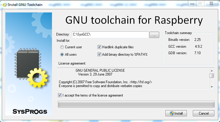
Due to the Unix roots for cross compilers, you need to set an installation directory without spaces in any directory name. This rules out the typical Windows Program Files directory. I selected C:\SysGCC.
The installation takes several minutes, even on a fast PC as there are a large number of files involved. There will not be any icon for the desktop as the tools are for command line use.
That's it, your tools will be placed in the directory you specified. Remember the location.
The cross compiler will not have the latest libraries for the Raspberry Pi that are included in the Raspbian Jessie distribution. These areneeded as they are linked in, used by the compiler to add pre-built functionality to a program at compile time. The easiest way to get a fresh set is to copy over the files from specific directories on an up to date Raspberry Pi. This will be done in the next post.
Cross Compiling is the process of making an executable program for one computer with the goal of running the program on another (different) computer. This can be very handy! Your desktop or laptop is probably more capable than your Raspberry Pi or other development device. Your PC has the edge with a better display, more memory, and speed.
With compiled programs like C and C++, this can be a more ideal procedure when compared to Python which is interpreted on the fly (thus no speed increase by doing compilation beforehand). Many people are familiar with C and C++ as the basis for the programming when using the Arduino development environment.
The diagram below shows how this would be accomplished.
The open source gcc compiler can generate code for many different computers. What we are looking for in this series is a Windows executable compiler which generates Raspberry Pi executables. There are many more combinations. Raspberry Pi cross compilers most often use Linux as the PC-side operating system and you can find Mac hosts as well.
Unfortunately, getting the cross compiler is not as simple as going to the Raspberry Pi website or GitHub repository (at present). The code for building the gcc toolchain (the programs that make up the cross compiler) is available but you need a native compiler (in this case Windows) and an environment that will take the source code and make the tools you want. Since gcc is a compiler that is Unix/Linux centric, you can set up an environment that helps Windows work more like *nix, the most common two being MinGW and Cygwin. This complicates the upfront work to set things up, something that we'd like to avoid at present.
The tutorial in following posts will demonstrate an effective cross compile process by using tools developed by SysProgs and Adafruit.
No sooner has the Raspberry Pi 3 been released, let's see about making it better. I'll point out a couple of items not widely discussed that may lead you to your hacking.
Unpopulated uFL Connector
The Raspberry Pi 3 has built-in Wi-Fi and Bluetooth. The standard antenna is a board mounted chip connector circled in red on the front side of the board below:
Front View
And look on the back below. The red circle shows the blank PCB area opposite the front chip antenna (you don't want parts here to avoid interference). All good.
Rear View
Now look at the 2 copper pads marked J13 circled in orange. The area between the copper squares is about the same area that would be occupied by a uFL antenna connection. What type of connection is that? uFL connectors are very small surface-mount parts used when an external RF antenna is desired. They used on GPS and Wi-Fi boards.
Close-up of pad J13 and a uFL solder connector (not to the same scale)
The solder mount uFL connector shown at right above are available for around a dollar at many electronics outlets. Most of those same outlets have inexpensive external antennas to connect to the uFL connector. Be careful, these connectors are somewhat fragile (they bend or crush if the mating plug is pushed on wrong). You can also find uFL to SMA and uFL to RP-SMA adapter cables to use larger antennas or use panel mount antennas.
Touch Screen Connector
The rear picture above has a spot shown in yellow. This is opposite the HDMI connector on the front. It is not shown with any part soldered there above and on the Raspberry Pi 2. But the FCC testing picture of the rear shows a ribbon cable connector on the board.
Leaked Raspberry Pi 3 FCC Testing Board with Populated Connector
This connector is similar to the one used on the interface board for the Raspberry Pi official 7 inch touchscreen display. I suspect this is for a touch interface but it is not documented or labelled. Other iterations of the Pi have had test points here. Why does this get so much attention but no parts or documentation? It's up to us to us. Do note that hardware modifications may void your warranty or change the wireless certification. . .
There is so much potential to this third generation board. Let me know if you have found things to do with it.
Ever wish you could prototype a Raspberry Pi program as easily as prototyping on Arduino?
The Arduino IDE allows nearly any processor to be programmed with the same easy to use language. Back in 2012, this was possible: it takes architecture changes by the Arduino group (arduino.cc), some programming by code library developers (adafruit.com, sparkfun.com, many others), and from users to get all of this working.
The parts are now in place to do this: the latest Arduino IDE releases are in a new 1.6.x branch, the latest as of this article is 1.6.3. This release is revolutionary in having the following:
A new library manager - libraries can be installed with several clicks from a website without downloading code and installing it in a specified place on the user's PC.
The capability to specify new boards that are not quite the same as Arduino boards. Companies have done this by hacks and creating special versions of the Arduino IDE which can get confusing after a bit.
A mechanism to easily specify and use code compilers other than the Atmel AVR. The Atmel SAM series is available after installing the 1.6.3 version if you request it.
In the same manner as the SAM (Arduino Due) capability can now be an add-on once the initial IDE is installed, other companies are working (quickly) to add the capability to incorporate their products. Obvious candidates include:
Non-Arduino Atmel AVR boards
Arduino "compatibles" - like the Teensy series which is very popular
Boards based on ARM cores Cortex M0, M0+, M3, etc.
Take this a step further. While running "simple minded microcontroller code" on more powerful boards seemed nonsensical not long ago as cost inefficient, those costs have plummeted. Development boards using powerful processors have come down in price thanks to Raspberry Pi, BeagleBone, and many others. The $50, $35, $25, $12, and $8 price points all have different boards that can be used. Even at $2 to $5, new boards like the ESP8266 Wifi controller are coming in. So, extend your thought to using the Arduino IDE to actually run Arduino code (not just program an AVR) on:
Some will say "Why Arduino?" The Arduino IDE and language specification, started in 2005 and extended since, has a proven track record for allowing users to easily get code running that actually interacts with the "real world". Millions of lines of Arduino code have been released under open source licenses, allowing reuse by anyone. With such a vast repository, why not leverage this onto other microcontroller and microcomputer architectures? With the compatibility to use C and C++ code, it is even more compelling.
Raspberry Pi as an Arduino Target
If I have some interesting Arduino code, say for controlling a near-field card reader, and wanted to port this to Raspberry Pi, I'd face a tough choice. Think about reprogramming in Python and hope there is manufacturer library support for Python, or consider programming in C and know that I'd have to rewrite the Arduino library to work on the Pi. Unsavory choices.
If the Arduino IDE would create a Raspberry Pi Linux executable of my Arduino sketch (program), I'd be nearly done. Due to differences in programmable pin (GPIO) numbering, some items would require changes but those are numbers and not wholesale code structure changes.
This could increase (rapidly) the available uses for a Raspberry Pi.
With a huge body of Open Source coders who may have the interest and time, I looks like there will be many more places where we will see Arduino code running.
Several items for today. First, Microcenter is continuing their expansion into electronics.
Pi now served at Microcenter (White Boxes)
Their stock of Raspberry Pi is complete with many Model B units (in slim and large boxes) at $39.99. Digging in, I found 3 Model A units among the others at $29.99. I found three cases (lower left) elsewhere and moved them to the same shelf. Their semi-monthly circular is due soon, I have a feeling they might discount the Pi. I picked up one of the $5.99 Digisparks to play with :-)
They have expanded their stock of Sparkfun products.
Sparkfun blister packs at Microcenter
They also have many kits by NightFire Electronics. New to me. Their website to browse is at http://vakits.com/.
Finally I picked up one of the Digispark boards as I did not get in on the Kickstarter as it was my early days rediscovering electronics.
Raspberry Pi Camera Arrives
I'll hand it to Newark/Element 14, they are efficient at filling Raspberry Pi camera orders. They shipped in an envelope that was crushed a bit and not fully sealed but everything was there. Projected project: A wifi camera for outside if I can find a case to hold it without getting wet. Ideas?
The camera is smaller than I expected
This week from China
I order some parts from China when I am not in a hurry and want good prices. This week I received an RS232 TTL to signal level converter board using the MAX3232. Not bad for $1.25 shipped via eBay.
Newark/Elemnt 14 sent emails to customers today to have them register their interest in the upcoming Raspberry Pi camera module.
From the email:
Are you ready for the all-new Raspberry Pi Camera Module?
Coming Soon! The Raspberry Pi Camera Module is a custom designed add-on for Raspberry Pi. It attaches to Raspberry Pi by way of one of the small sockets on the board upper surface. This product uses the dedicated CSi interface, designed especially for connecting to cameras. The board itself is tiny, at around 25mm x 20mm x 9mm.
5 megapixel native resolution sensor-capable of 2592 x 1944 pixel static images
Supports 1080p30, 720p60 and 640x480p60/90 video
Camera is supported in the latest version of Raspbian, Raspberry Pi's preferred operating system
As you can see from the picture, they had not even put them on the shelf, they were in the ubiqitous "new stock pile cart". As the store was undergoing renovation (taller shelves, more room for more stuff), I will not complain too much as I hope they expand the electronics parts area.
Tandy, the UK electronics company, is introducing an electronics kit compatible with the Raspberry Pi Getboard experimenters board.
The Gertboard is no longer available in kit form but has come out as an assembled board available from a number of vendors including Sparkfun.
I am glad to see the Gertboard receive a resurgence after the initial kit issue and subsequent withdraw from the market. I would love to see some experiments or projects using these boards.
The "Raspberry Pi to Arduino shields connection bridge" is a Raspberry Pi add-on allowing you to use some of the shields, boards and modules designed for Arduino on a Raspberry Pi. It includes also the possibility of connecting digital and analog sensors, using the same pinout of Arduino but with the power and capabilities of a Raspberry Pi.
The "Raspberry Pi to Arduino shields connection bridge" board on top of a Raspberry Pi computer
To allow for software programming, cooking-hacks.com has written the arduPi C/C++ library allowing a Raspberry Pi to use the same code used in Arduino. To do so, they implemented conversion functions to control the hardware in the same way as in Arduino the same I/O interfaces: i2C, SPI, UART, analog, digital, on a Raspberry Pi.
What may be done with the shield along with the arduPi library:
Connect sensors (analog 0-5V, digital) to Raspberry Pi with a precession of 16b using the ADC integrated. Connect also complex sensors through i2C and UART buses
Connect some electronic module or actuator which works over i2C, SPI, UART
I have used the word some when the site uses any. Buried down on the page is this warning:
WARNING: GPIO voltage levels are 3.3 V and are not 5 V tolerant. There is no over-voltage protection on the board. Digital inputs use a 3V3 logic level and are not tolerant of 5V levels, such as you might find on a 5V powered Arduino. Extreme caution when working with GPIO, you may damage your Raspberry Pi, your equipment and potentially yourself and others.
As most shields have 5 volt signals, this could be a large limitation. The number of 3.3 volt shields is expected to grow, albeit slowly, with hardware using sensing to be compatible with hardware like the new Arduino Due.
I like the Bee socket. Many types of hardware have been made in this form factor - usually at 3.3 volts like the XBee.
At 40 euros, it is rather overpriced for the US market.
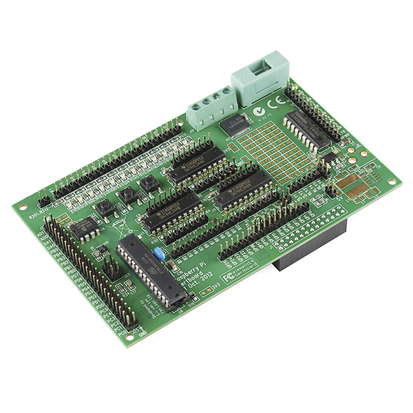
The Gertboard was the first add-on board announced for the Raspberry Pi. It was delayed a number of times but finally was released as a kit for a limited time from Europe. Now the second wave has arrived in the US via a complete board from Sparkfun Electronics.
Gertboard October 2012 ("Version 2")
The design is rather bold - rather than having a few functions, the board has many features including a AVR (Arduino type) helper controller. It has GPIO buffers and motors. Finally it has an 8 bit dual channel digital to analog converter and a dual channel analog to digital converter.
The October 2012 branded version design differs from the March 2012 DIY board. The ribbon cable to connect to the Raspberry Pi is now a direct connect stackable header. The fuse for the motor driver is enclosed and a different motor driver chip used, More surface mount parts are used including the voltage regulator and LEDs.
Gertboard March 2012 ("Version 1")
This board is a fantastic way to experiment with the Raspberry Pi - out of the box, the Pi is rather limited on connection capabilities. The Gertboard opens up the capabilities to perform nearly any function one might want to do: control, robotics, sensing.
It still does not allow connection of Arduino compatible shields as it uses a proprietary dual row header. This can be adapted though not directly. The Breadboard Shield Adapter brings an Arduino shield pins to one side where one would have to manually connect the various pins. Not perfect but doable. Maybe the next revision of the Gertboard will allow for a better connection.
Breadboard Shield Adapter
These boards should see adoption in schools and other learning situations and hobbyists who want to tinker around. Hopefully mopre projects will be published using the board. The link to get one from Sparkfun is https://www.sparkfun.com/products/11773