Showing posts with label Tinkerkit. Show all posts

Sunday, March 24, 2013

Reading the Arduino Esplora Tinkerkit Inputs

The Esplora is expandable via two Tinketkit Outputs and two Tinkerkit Inputs.  At present the Arduino IDE does not have code to easily use these connectors.  This post will provide information on how you can read the inputs before the Arduino team releases their code.
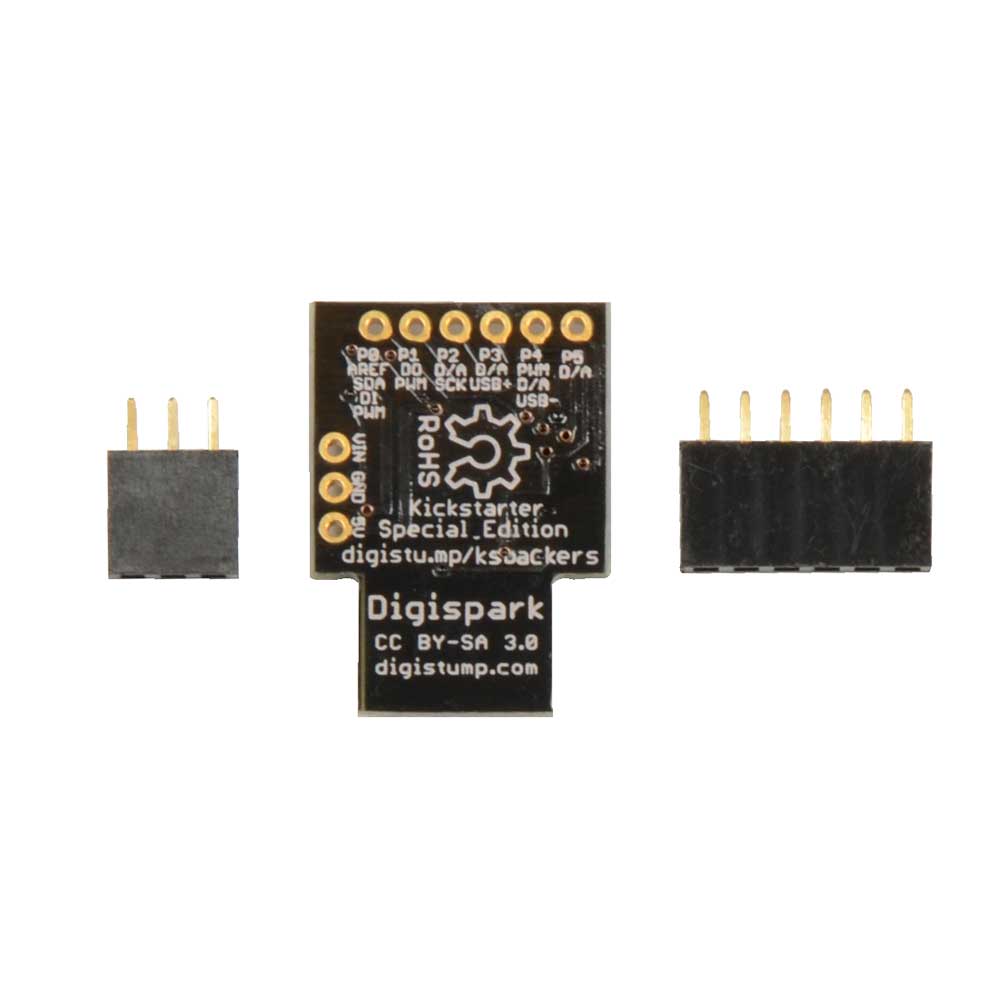
The two white Esplora Tinkerkit Inputs IN-A and IN-B to the right of the USB cable
The two Tinkerkit Inputs are the white three-pin connectors to the right of the USB port.  They cannot be read directly by analogRead as they are connected through the Esplora's 74HC4067D multiplexer chip.  The multiplexer allows more sensors to connect to the ATMEGA 32U4 microcontroller.  The multiplexer address lines are connected to the ATMEGA logical analog lines A0, A1, A2, and A3.  The result is read on A4 when the address lines point to the desired input.

/*
  Esplora Tinkerkit Input Read

 This sketch shows you how to read the Tinkerkit Inputs on the Arduino Esplora.
 Most likely this program will become obsolete when the Arduino team updates the IDE beyond 1.04

 Created on 2013-03-24 by Mike Barela

 This example is in the public domain, please attribute
 */

#include <Esplora.h>
#if ARDUINO < 105
const byte CH_TINKERKIT_INA = 8;   // Add values missing from Esplora.h
const byte CH_TINKERKIT_INB = 9;
const byte INPUT_A          = 0;
const byte INPUT_B          = 1;

unsigned int readTinkerkitInput(byte whichInput) {      // return 0-1023 from Tinkerkit Input A or B
   return readChannel(whichInput+CH_TINKERKIT_INA); }   //   as defined above
 
unsigned int readChannel(byte channel) {                // as Esplora.readChannel is a private function
     digitalWrite(A0, (channel & 1) ? HIGH : LOW);      //  we declare our own as a hack
     digitalWrite(A1, (channel & 2) ? HIGH : LOW);      //
     digitalWrite(A2, (channel & 4) ? HIGH : LOW);      // digitalWrite sets address lines for the input
     digitalWrite(A3, (channel & 8) ? HIGH : LOW);
     return analogRead(A4);               // analogRead gets value from MUX chip
}
#endif

void setup() {
  // initialize the serial communication:
  Serial.begin(9600);
}

void loop() {
  // read the sensor into a variable:
  unsigned int input_a_value = readTinkerkitInput(INPUT_A);
  unsigned int input_b_value = readTinkerkitInput(INPUT_B);

  // print the input values to serial monitor

  Serial.print("Input A: ");
  Serial.print(input_a_value);
  Serial.print(", Input B: ");
  Serial.println(input_b_value);
  // add a delay between readings (not required in general)
  delay(1000);
}


The Tinkerkit Inputs are on multiplexer addresses 8 and 9.  These are not defined in the esplora.h file as of IDE version 1.04.  Also the function used to read an inputs from the multiplexer, readChannel.  So these are recreated in the example above.  Every second, IN-A and IN-B are read then printed to the serial monitor.  As you see in the picture above, the IN-A data pin (center) is connected to +5 volts left pin).   The IN-B data pin is connected to the ground pin on the left).  This produces 1023 for IN-A and 0 for IN-B.  Note: if you have nothing connected to an input, it will return a random value between 0 and 1023 like any analog input.

The two Tinkerkit outputs are to the left of the USB connector and are orange.  If you wish to read or write to them it is more straightforward.  OUT-B is on Arduino logical pin D11 and OUT-A is on pin D3.  These are digital pins but they are pulse width modulation enabled so analogWrite works also.  Previous programs on this site have used these connectors to send data, mainly to an xbee.  See this one for more.

If you are interested in other Esplora articles on this website, a list is here.

Thursday, March 21, 2013

Digispark and Tinkerkit now at Microcenter

I went trolling at our local Microcenter store's Maker section.  Besides $14.99 Arduino Unos, I was surprised to see additional items added to their lineup:

First is the Digistump Digispark line.  Started on Kickstarter, these boards are wonderful for smaller projects  both in low prices and big flexibility.  The board is $9.99 and they have a full line of shields.


Second is the Arduino Tinkerkit line.  Formerly only available on the www.tinkerkit.com and Arduino.cc stores (and priced in expensive Euros), now we have them in the US.  While not as good a value as other parts, they have them including some sets and individual sensors.  I did NOT see any of the connecting cables which would limit the ability to use them.  Get your Arduino Esplora at Radio Shack and consider adding Tinkerkit components.

SO Microcenter is becoming quite a player in the Makerspace.  I would like to see them organize their products so they are easier to browse.  But overall I'll take quantity over quality.

Saturday, January 19, 2013

Arduino Esplora Tinkerkit Outputs

The new Arduino Esplora has two orange output connectors at the top left of the device.  They have been identified as for connection to Tinkerkit devices.  I'm here to help the hacker use these connectors like they might on traditional Arduinos.
Turning it sideways and magnifying:

To connect, you'll want 3-pin molex connectors.  They are commonly used for PC fans.  You can find them at Sparkfun Electronics and other suppliers.  If you make your own connector, take the pins off, crimp a wire on, solder, then gently slip it in bump side upto the molex hole side up until it clicks in.  If you need to remove pins, get a paper clip tip and gently press on the pin through the connector while gently tugging out.  The completed molex connector will slide onto the orange male on the Esplora and click on.  To take your connectors off the Esplora, you might have to pry on the orange molex tab, then wiggle your female connector off.

Once you have connectors wired, connect to your devices or sensors.  Left, I show connecting an XBee on a Sparkfun XBee Explorer Regulated breakout board which handles the power step down to 3.3 volts for the Bee and the 5 volt to 3.3 volt signal line difference.  With my setup, I can use the SoftwareSerial library to define a software serial connection.  See http://arduino.cc/en/Reference/SoftwareSerial  for more information.


Programming: the pins are used as any digital pin in the Arduino software.  They are digital pin 3 and digital pin 11.  Both support pulse-width modulation (PWM) so you can connect LEDs, servos, etc. and vary the pulses to brighter/speedup or dim/slow down your connected device (usually done with analogWrite even though it is a digital pin). Do NOT connect a regular (non-Tinkerkit) servo directly to the pins, the pinout is different.  See http://arduino.cc/en/Reference/AnalogWrite for more information.  As with all connections, be careful of the power you draw.

You can power the Esplora by putting 5 volts into the Tinkerkit connectors.  I highly suggest you ensure the polarity is correct several times before you actually do this as a reversed connection could destroy your device.  I (carefully) do this using a LiPo battery circuit described in a previous post.

If you need more digital pins for your project than these two, you can use the ones that have been reserved for a display.  See this post for more information.

Let me know what projects you build with these connectors.