Today I saw a Google+ post on Bodhi Linux. Bodhi Linux is a linux distribution leveraging the fast, customizable, and elegant Enlightenment Desktop. Based on Ubuntu, it is available for the Raspberry Pi (hard floating point).
The minimum requirements to run Bodhi Linux are only: 300+ MHz CPU, 128 MB RAM, and 2.5 GB hard drive space.
Minimalism is one of Bodhi Linux's two core ideals. The combination of Enlightenment and the core utilities included in a default Bodhi Linux install lead to exceptional speed and low system requirements, while providing a usable and customizable desktop experience. User choice is another important feature embodied in Bodhi Linux. By only including a small set of default utilities, the user is free to make Bodhi Linux their operating system. Users can install applications from our extremely easy to use AppCenter, apt-get, or Synaptic to suit their individual needs.
Bodhi is based on the very efficient NeXTStep design, invented by Scott Forestall, the former Apple chief software architect. It still runs very fast even on oldest computers, e.g. a 68030 with only 32 MByte RAM. And it natively supports OpenGL hardware. See https://en.wikipedia.org/wiki/NeXTStep for more.
Small drawback: It's written in Objective-C. Objective-C is pure C, plus Smalltalk pipes for interprocess communication, for sharing data. Smalltalk is a communication oriented language, where 'state' is kept in small 'objects'. What these 'living objects' can understand or send, is coded in 'classes' and 'methods'. The language itself consists of just 5 elements - extremely easy to learn. Porting apps from MacOS X or iOS is simple. Included in EFL (Enlightenment Foundation Library) is the complete SDK with GUI builder.
If you're a person who wants to decide themselves how to run your Pi, this distro may be the one for you.
Download link: http://www.bodhilinux.com/downloads_mobile.php (scroll down to Raspberry Pi version)
The Esplora is expandable via two Tinketkit Outputs and two Tinkerkit Inputs. At present the Arduino IDE does not have code to easily use these connectors. This post will provide information on how you can read the inputs before the Arduino team releases their code.
The two white Esplora Tinkerkit Inputs IN-A and IN-B to the right of the USB cable
The two Tinkerkit Inputs are the white three-pin connectors to the right of the USB port. They cannot be read directly by analogRead as they are connected through the Esplora's 74HC4067D multiplexer chip. The multiplexer allows more sensors to connect to the ATMEGA 32U4 microcontroller. The multiplexer address lines are connected to the ATMEGA logical analog lines A0, A1, A2, and A3. The result is read on A4 when the address lines point to the desired input.
/*
Esplora Tinkerkit Input Read
This sketch shows you how to read the Tinkerkit Inputs on the Arduino Esplora.
Most likely this program will become obsolete when the Arduino team updates the IDE beyond 1.04
Created on 2013-03-24 by Mike Barela
This example is in the public domain, please attribute
*/
unsigned int readTinkerkitInput(byte whichInput) { // return 0-1023 from Tinkerkit Input A or B
return readChannel(whichInput+CH_TINKERKIT_INA); } // as defined above
unsigned int readChannel(byte channel) { // as Esplora.readChannel is a private function
digitalWrite(A0, (channel & 1) ? HIGH : LOW); // we declare our own as a hack
digitalWrite(A1, (channel & 2) ? HIGH : LOW); //
digitalWrite(A2, (channel & 4) ? HIGH : LOW); // digitalWrite sets address lines for the input
digitalWrite(A3, (channel & 8) ? HIGH : LOW);
return analogRead(A4); // analogRead gets value from MUX chip
}
#endif
void setup() {
// initialize the serial communication:
Serial.begin(9600);
}
void loop() {
// read the sensor into a variable:
unsigned int input_a_value = readTinkerkitInput(INPUT_A);
unsigned int input_b_value = readTinkerkitInput(INPUT_B);
// print the input values to serial monitor Serial.print("Input A: ");
Serial.print(input_a_value);
Serial.print(", Input B: ");
Serial.println(input_b_value);
// add a delay between readings (not required in general)
delay(1000);
}
The Tinkerkit Inputs are on multiplexer addresses 8 and 9. These are not defined in the esplora.h file as of IDE version 1.04. Also the function used to read an inputs from the multiplexer, readChannel. So these are recreated in the example above. Every second, IN-A and IN-B are read then printed to the serial monitor. As you see in the picture above, the IN-A data pin (center) is connected to +5 volts left pin). The IN-B data pin is connected to the ground pin on the left). This produces 1023 for IN-A and 0 for IN-B. Note: if you have nothing connected to an input, it will return a random value between 0 and 1023 like any analog input.
The two Tinkerkit outputs are to the left of the USB connector and are orange. If you wish to read or write to them it is more straightforward. OUT-B is on Arduino logical pin D11 and OUT-A is on pin D3. These are digital pins but they are pulse width modulation enabled so analogWrite works also. Previous programs on this site have used these connectors to send data, mainly to an xbee. See this one for more.
If you are interested in other Esplora articles on this website, a list is here.
I went trolling at our local Microcenter store's Maker section. Besides $14.99 Arduino Unos, I was surprised to see additional items added to their lineup:
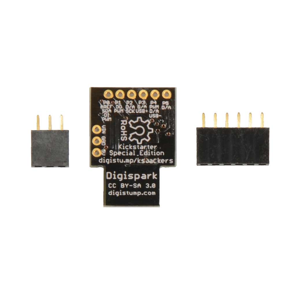
First is the Digistump Digispark line. Started on Kickstarter, these boards are wonderful for smaller projects both in low prices and big flexibility. The board is $9.99 and they have a full line of shields.
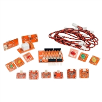
Second is the Arduino Tinkerkit line. Formerly only available on the www.tinkerkit.com and Arduino.cc stores (and priced in expensive Euros), now we have them in the US. While not as good a value as other parts, they have them including some sets and individual sensors. I did NOT see any of the connecting cables which would limit the ability to use them. Get your Arduino Esplora at Radio Shack and consider adding Tinkerkit components.
SO Microcenter is becoming quite a player in the Makerspace. I would like to see them organize their products so they are easier to browse. But overall I'll take quantity over quality.
Like many kids growing up in the late 60's and 70's, Saturday mornings were spent watching cartoons. Not much learning except Schoolhouse Rock, it was full of Hanna Barbera cartoons like Scooby Doo and Jonny Quest.
Jonny Quest had the best story line - kids would be around their scientific dad and his action bodyguard.
The thing is: alot of cool technology was presented, fueling many kids to become engineers and scientists.
So in the vein if "all I learned I got from...", here is a list of Jonny Quest technologies and what we have today:
The Robot Spy was a spider-like robot with an electric eye. Today we have hexapod robots with sensors. While the sizes are different, we're on our way to achieving this one.
The laser was just a lab experiment years ago but on Jonny Quest the laser was already a weapon. Today's article is the US Navy will make 2013 the year of the laser gun.
While the Quest jet is not ubiquitous today, the vertical takeoff and landing is in several planes today.
Jonny's small boats were precursors to today's jet skis.
While we don't have personal jet packs yet, would you trust people to have them? They can be seen at fair grounds and on the Six Million Dollar Man but this one wasn't to be commonplace.
I won't go into the case of the invisible electricity monster - I fear creating that every time I look through the Sparkfun parts list.
The EMIC 2 speech processing module allows any Maker to add spoken word capability to a project. The board is designed by Grand Idea Studio and marketed by Parallax, having been released last July. It is carried by Maker Shed, Adafruit, and most recently Sparkfun.
I wanted to make the simplest connection between a Windows laptop to the module. My setup consists of an iteadstudio.com Foca 2.1 board to convert the PC USB connection to a TTL level serial connection. Other USB to serial options would be a 3.3 volt or 5 volt FTDI Friend cable or other USB to serial boards on the market. I like the Foca as it is also a USB to Xbee adapter and works at dual voltages (and only costs $7.50 compared to $20 for the single use, single voltage FTDI friend.
The Foca is set for 5 volts but the EMIC 2 module works at 3.3 volt signal levels also
If your USB to serial connection cannot provide at least 220 milliamps then you will need an external power supply to power the EMIC. The typical USB port can supply 500 milliamps. The Foca current rating is not published but worked well in testing.
The connections are made via a female to female multiconductor cable (a couple of dollars on Ebay, also at Adafruit). Connect the 5 volts and ground from the serial connection to the EMIC board. The transmit pin on the serial board goes to the receive pin (SIN) on the EMIC. Likewise the serial receive pin connects to the EMIC data output (SOUT) pin.
EMIC 2 connections: Ground, 5 volts, SOUT, SIN, and speaker pins. The white cable is the audio output.
Sound output can be via an 8 ohm speaker from the two remaining EMIC 2 pins or via the mini jack. I connected the EMIC board via a mini plug cable (white) to an amplified speaker I had in the shop (an antique Radio Shack amplified speaker). Headphones or another type of amplifier would work also.
Double check your connections (twice). Plug the USB cable into the PC and the EMIC board LEDs should light, first colors then green if ready. If you do not have lights, unplug and check your connections.
You may then talk to the EMIC module via a PC terminal program. PuTTY is free and configurable. Use your favorite. Set the communication to 9600 baud, 8 bits, 1 stop bit, no parity. It would help to set local echo and Carriage Return is Line Feed and visa versa to make display easier for you.
A PuTTY terminal on the left, the EMIC 2 data sheet on the right for commands.
The commands to have the unit talk are in the datasheet. The nest test is to type D0 (the letter D then the number zero). The EMIC will then run through its test dialog in English. D2 will speak in Spanish. If you wish to speak a sentence, preface it by the letter S. You can change the voice using the command N followed by a number from 0 to 7. All have a mechanical sound but are quite good.
Youtube video of the project:
This is a fun module - it takes me back to the speech heyday where the home had a speak-n-spell and the work computer had a DECtalk box. The EMIC 2 actually will emulate a DECtalk and that command set allows for fine control of the voice process. The DECtalk box came out in 1984 at a price of $4,000. The EMIC 2 is available for about $59.99 (less with 10% off sales, Saturday nights on Adafruit, randomly at Maker Shed).
Next: Incorporate the EMIC into projects - I had thought of adding it to my robotic head projects but I would like a talking alarm system more.
I have a vintage speech system I made in 1985. I'll blog on that soon.
PS Sorry for the pink background, I had previously fixed an older Dell laptop and it made a handy platform.